Instructions:
- The marks are indicated in the right-hand margin.
- There are NINE questions in this paper.
- Attempt FIVE questions in all.
- Question No. 1 is compulsory.
Q.1 Choose the correct option/answer the following (Any seven questions
only):
The function of an MCB is to protect against
The EMF induced in a transformer, if $ f=50~Hz $, $ N=1000 $ turns, $ \varphi_m=0.001 $ Wb.
The short-circuit test is conducted to determine
The torque of a DC motor is directly proportional to
If an RL circuit has $ R=10~\Omega $, $ L=5~H $ and is connected to 20V DC, the final current after a long time is
The synchronous speed for a 4-pole, 50 Hz motor is
If a delta network has each branch of $ 9~\Omega $, the equivalent star resistance is
A purely inductive circuit has
Which of the following is an active element
The power factor of a pure capacitor is
Q.2 Solve both questions:
Describe the plate earthing and pipe earthing methods in detail. Compare their advantages and disadvantages.
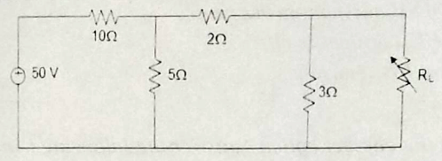
In the circuit given below, the maximum power delivered to the load ($ R_L $) is.
Q.3 Solve both questions:
Compare DC motors, induction motors, and synchronous machines in terms of torque, speed control, and applications.
Explain the criteria for selecting the size of wires and cables for electrical installations. Discuss the effects of overloading and voltage drop.
Q.4 Solve both questions:
A 3-phase induction motor has a full-load slip of 4%. If the supply frequency is 50 Hz, find the rotor speed and rotor frequency at full load.
What is an Earth Leakage Circuit Breaker (ELCB)? Explain its working principle and importance in protecting human life and equipment.
Q.5 Solve both questions:
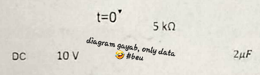
The switch is closed at $ t=0 $ find the voltage across the capacitor $ V_c $ at $ t=7ms $
Derive an expression for the energy stored in a magnetic field.
Q.6 Solve both questions:
Derive the torque equation of a DC motor and explain the torque-speed characteristic.
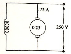
A 250-V shunt motor giving 14.92 kW at 1000 r.p.m. takes an armature current of 75 A. The armature resistance is 0.25 ohms, and the load torque remains constant. If the flux is reduced by 20 percent of its normal value before the speed changes, find the instantaneous value of the armature current and the torque. Determine the final value of the armature current and speed.
Q.7 Solve both questions:
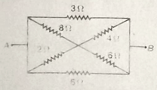
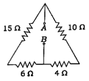
Find the equivalent resistance between terminals A and B.
Derive the EMF equation of a single-phase transformer.
Q.8 Solve both questions:
Define voltage regulation and derive its expression.
What are hysteresis and eddy current losses? Discuss their effects on magnetic materials.
Q.9 Write short notes on any two of the following:
Power triangle
Auto-Transformer
Thevenin's Theorem
Explain why the rating of the transformer is in KVA but not in KW.
Instructions:
- The marks are indicated in the right-hand margin.
- There are NINE questions in this paper.
- Attempt FIVE questions in all.
- Question No. 1 is compulsory.
Q.1 Choose the correct option/answer the following (Any seven question
only):
Kirchhoff's Current Law is based on
In a bilateral element, voltage-current relation
Eddy current loss can be reduced by
A circuit with low power factor draws
Superposition theorem is not applicable to networks containing
Transformer efficiency is maximum when
A good solder joint should be
Transformer works on
Permeability is highest in
The rms value of a sinusoidal voltage with peak-to-peak value of 240 V is
Q.2 Solve both questions :
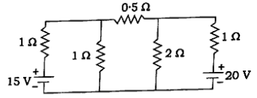
Determine the value of current flowing through the 10 $ \Omega $ resistor for given circuit:
State and explain the Maximum Power Transfer Theorem, and derive the condition under which maximum power is delivered to the load.
Q.3 Solve both questions :
Define delta network and star network and derive the formulae to convert a delta network into its equivalent star network.
A voltage wave has the variation shown in figure.
(i) Find the average and effective values of the voltage.
(ii) If this voltage is applied to a 10 $ \Omega $ resistance, find the dissipated power.

Q.4 Solve both questions :
A 100 W resistor is connected in series with a choke coil. When a 400 V, 50 Hz supply is applied to this combination, the voltages across the resistance and the choke coil are 200 V and 360 V respectively. Find the power consumed by the choke coil. Also, calculate the power factor of the choke coil and the power factor of the circuit.
Define and find the expression for the condition of resonance, bandwidth and quality factor of a series R-L-C circuit.
Q.5 Solve both questions :
Derive the relationship between phase and line quantities (voltage, current) for a balanced three-phase delta-connected system. Also draw neat diagrams.
Three similar coils each having a resistance of 10 $ \Omega $ and inductance of 0.04 H are connected in star across 3 phase, 50 Hz, 200 V supply. Calculate the line current, total power absorbed, reactive volt amperes and total volt amperes.
Q.6 Solve both questions :
Derive an emf equation for a single-phase transformer and explain voltage and current ratio of an ideal transformer.
A 250 kVA, 50 Hz single-phase transformer has ratio of secondary to primary turns as 0.1. The secondary voltage at no-load condition is 240 V. Calculate (i) primary voltage and (ii) full load primary and secondary currents.
Q.7 Solve both questions :
Explain the working principle of DC generator and derive expression for the emf of a DC generator.
Explain the working principle and operation of Three Phase Induction Motor.
Q.8 Solve both questions :
Explain the steps involved in proper soldering and desoldering of electronic components.
Explain the difference between breadboard wiring and PCB wiring with advantages and limitations.
Q.9 Write short notes on any four of the following:
Residential and Commercial wiring systems.
Superposition Theorem
Hysteresis and Eddy Current losses
Power factor improvement
Power Triangle
Instructions:
- The marks are indicated in the right-hand margin.
- There are NINE questions in this paper.
- Attempt FIVE questions in all.
- Question No. 1 is compulsory.
Q.1 Choose the correct option/answer the following (Any seven question
only):
Kirchhoff's Current Law is based on
In a bilateral element, voltage-current relation
Eddy current loss can be reduced by
A circuit with low power factor draws
Superposition theorem is not applicable to networks containing
Transformer efficiency is maximum when
A good solder joint should be
Transformer works on
Permeability is highest in
The rms value of a sinusoidal voltage with peak-to-peak value of 240 V is
Q.2 Solve both questions :
Determine the value of current flowing through the 10 $ \Omega $ resistor for given circuit:

State and explain the Maximum Power Transfer Theorem, and derive the condition under which maximum power is delivered to the load.
Q.3 Solve both questions :
Define delta network and star network and derive the formulae to convert a delta network into its equivalent star network.
A voltage wave has the variation shown in figure.
(i) Find the average and effective values of the voltage.
(ii) If this voltage is applied to a 10 $ \Omega $ resistance, find the dissipated power.
Q.4 Solve both questions :
A 100 W resistor is connected in series with a choke coil. When a 400 V, 50 Hz supply is applied to this combination, the voltages across the resistance and the choke coil are 200 V and 360 V respectively. Find the power consumed by the choke coil. Also, calculate the power factor of the choke coil and the power factor of the circuit.
Define and find the expression for the condition of resonance, bandwidth and quality factor of a series R-L-C circuit.
Q.5 Solve both questions :
Derive the relationship between phase and line quantities (voltage, current) for a balanced three-phase delta-connected system. Also draw neat diagrams.
Three similar coils each having a resistance of 10 $ \Omega $ and inductance of 0.04 H are connected in star across 3 phase, 50 Hz, 200 V supply. Calculate the line current, total power absorbed, reactive volt amperes and total volt amperes.
Q.6 Solve both questions :
Derive an emf equation for a single-phase transformer and explain voltage and current ratio of an ideal transformer.
A 250 kVA, 50 Hz single-phase transformer has ratio of secondary to primary turns as 0.1. The secondary voltage at no-load condition is 240 V. Calculate (i) primary voltage and (ii) full load primary and secondary currents.
Q.7 Solve both questions :
Explain the working principle of DC generator and derive expression for the emf of a DC generator.
Explain the working principle and operation of Three Phase Induction Motor.
Q.8 Solve both questions :
Explain the steps involved in proper soldering and desoldering of electronic components.
Explain the difference between breadboard wiring and PCB wiring with advantages and limitations.
Q.9 Write short notes on any four of the following:
Residential and Commercial wiring systems.
Superposition Theorem
Hysteresis and Eddy Current losses
Power factor improvement
Power Triangle
Instructions:
- The marks are indicated in the right-hand margin.
- There are NINE questions in this paper.
- Attempt FIVE questions in all.
- Question No. 1 is compulsory.
Q.1 Choose the correct answer the following (Any seven question
only):
Ohms law is applicable to
The condition for maximum power transfer from a voltage source to load is
The time constant of RL circuit is?
The superposition theorem is used when the circuit contains.
The power factor in an AC circuit is defined as the ratio of:
If 20, 30, and 50 ohms are connected in delta connection, then what are its equivalent values (in ohms) in star connection?
In a balanced three-phase system, the phase difference between any two phases is:
The main function of the commutator in a DC machine is to:
In a series RLC circuit, resonance occurs when:
Which tool is commonly used for desoldering?
Q.2 Solve both questions :
State and prove Maximum Power Transfer Theorem for a DC network. Calculate the maximum power for a given network.
[Question text missing from original document, likely related to circuit analysis]
Q.3 Solve both questions :
State Norton's Theorem and draw the Norton's equivalent circuit.
Discuss the difference between ideal and practical voltage and current source. Differentiate among real, reactive and apparent power.
Q.4 Solve both questions :
Discuss the analogy between the electrical and magnetic circuit.
A resistor R ohms and capacitor 5$\mu$F are connected in series across a 200V dc supply. Calculate the value of R such that the voltage across the capacitor becomes 100V in 5 secs after the circuit is switched on.
Q.5 Solve both questions :
A coil has resistance of 7ohm and inductance of 3.18mH connected to 230V, 50Hz supply. Calculate: (i) phase angle (ii) power factor (iii) power consumed (iv) voltage drop across R and L.
Describe the idea behind phasors. How do phasors depict voltages and currents that fluctuate sinusoidally?
Q.6 Solve both questions :
What is power factor? Discuss its importance in electrical systems, causes of low power factor, and methods of improvement.
Describe the difference between star and delta connections.
Q.7 Solve both questions :
Explain the single-phase transformer's design and operation. Determine the EMF formula.
Describe the construction and working principle of a DC generator. Derive the EMF equation.
Q.8 Solve this question :
What are the general rules and guidelines for electrical installation in residential wiring? Include any relevant safety standards.
Q.9 Write short notes on any two of the following:
Instructions:
- The marks are indicated in the right-hand margin.
- There are NINE questions in this paper.
- Attempt FIVE questions in all.
- Question No. 1 is compulsory.
Q.1 Choose the correct answer of the following (Any seven question
only):
In source transformation, a voltage source in series with a resistor can be converted into:
According to Kirchhoff's Voltage Law (KVL), the sum of voltages around a closed loop is:
Which of the following is a bilateral element?
Which of the following quantities in a magnetic circuit is analogous to current in an electric circuit?
The power factor in an AC circuit is defined as the ratio of:
Which connection type has a neutral point?
In a DC generator, the EMF is generated due to:
Which of the following losses occurs in a transformer?
In a series RLC circuit, resonance occurs when:
The main function of a distribution board is to:
Q.2 Solve this question :
Explain Thevenin's and Norton's Theorems. How can one be derived from the other? Support your answer with a circuit diagram and step-by-step solution.
Q.3 Solve both questions :
State and explain Kirchhoff's Current Law (KCL) and Kirchhoff's Voltage Law (KVL) with an illustrative circuit and solve a simple numerical example.
Describe the process of source transformation and provide an example where a voltage source is transformed into a current source and vice versa.
Q.4 Solve both questions :
Describe the concept of magnetic reluctance and derive the formula for reluctance in terms of length, area, and permeability.
Explain the analogy between electric and magnetic circuits. Draw a table comparing the corresponding quantities.
Q.5 Solve both questions :
Define and compare average value, RMS value, form factor, and peak factor for sinusoidal waveforms. Give appropriate expressions and examples.
Explain the concept of phasors. How are sinusoidally varying voltages and currents represented using phasors?
Q.6 Solve this question :
Describe the difference between star and delta connections. Provide diagrams and explain voltage and current relations for both.
Q.7 Solve both questions :
Describe the construction and working of a single-phase transformer. Derive the EMF equation.
Explain the types of DC machines and differentiate between a DC motor and a DC generator.
Q.8 Solve this question :
Describe the different types of residential and commercial wiring systems with diagrams.
Q.9 Write short notes on any two of the following:
Instructions:
- The marks are indicated in the right-hand margin.
- There are NINE questions in this paper.
- Attempt FIVE questions in all.
- Question No. 1 is compulsory.
Q.1 Answer the following Questions (any seven only):
State Kirchoff's Current law and Kirchoff's Voltage Law.
Define Network and Circuit.
State Maximum Power Transfer Theorem.
State the steps to solve the super position theorem.
Write two differences between Real Power and Reactive Power.
Define Resonance.
Draw BH Characteristic of ferromagnetic material.
Write the types of DC Motor and Generator.
Why Earthing is important for an electrical Circuit?
What are the basic differences between generator and motor?
Q.2 Solve both questions :
Derive an expression for the current and impedance for a series RL and RC circuit excited by a Sinusoidally alternating voltage. Draw the Phasor diagrams.
A series circuit consisting of a $10\,\Omega$ resistor, a $100\,\mu\mathrm{F}$ capacitor and a $10\,\mathrm{mH}$ inductor is driven by a 50 Hz a.c. voltage source of maximum value 100 volts. Calculate the equivalent impedance, Current in the circuit and the phase angle.
Q.3 Solve both questions :
A load resistance $R_L\,\Omega$ is connected across the source $V_s$ with internal resistance $R_{\text{int}}$ in series with source. Obtain the condition that the power transferred to load from source is maximum.
A resistance $R$ is connected in series with a parallel circuit comprising two resistances of $12\,\Omega$ and $8\,\Omega$ respectively. The total power dissipated in the circuit is 70 W when the applied voltage is 20V. Calculate $R$.
Q.4 Solve both questions :
With neat diagram explain the construction and principle of a single-phase transformer. What are the characteristics of an ideal transformer?
Derive the emf equation of a transformer.
Q.5 Solve both questions :
Draw a neat sketch of a DC generator and label the component parts. Name the material used for each component part.
Explain the operating principle of Three phase Induction motor.
Q.6 Solve both questions :
With neat diagrams, explain various types of fuses used in electrical wiring systems.
Write a detailed note on Fuse and circuit breaker.
Q.7 Solve both questions :
State and Explain Thevenin's Theorem for a DC Circuit. Write applications, advantages and limitations of Thevenin's Theorem.
State Norton's theorem.
Q.8 Solve this question :
A three single phase balanced load connected in three phase three wires star form, with the help of phasor diagram, obtain the relationship between line and phase quantities of voltage and current.
Q.9 Write short notes on any two of the following:
Instructions:
- The marks are indicated in the right-hand margin.
- There are NINE questions in this paper.
- Attempt FIVE questions in all.
- Question No. 1 is compulsory.
Q.1 Answer the following Questions (any seven only):
State Kirchoff's Current law and Kirchoff's Voltage Law.
Define Network and Circuit.
State Maximum Power Transfer Theorem.
State the steps to solve the super position theorem.
Write two differences between Real Power and Reactive Power.
Define Resonance.
Draw BH Characteristic of ferromagnetic material.
Write the types of DC Motor and Generator.
Why Earthing is important for an electrical Circuit?
What are the basic differences between generator and motor?
Q.2 Solve both questions :
Derive an expression for the current and impedance for a series RL and RC circuit excited by a Sinusoidally alternating voltage. Draw the Phasor diagrams.
A series circuit consisting of a resistor, a capacitor and a inductor is driven by a 50 Hz a.c. voltage source of maximum value 100 volts. Calculate the equivalent impedance, Current in the circuit and the phase angle.
Q.3 Solve both questions :
A load resistance is connected across the source with internal resistance in series with source. Obtain the condition that the power transferred to load from source is maximum.
A resistance is connected in series with a parallel circuit comprising two resistances of and respectively. The total power dissipated in the circuit is 70 W when the applied voltage is 20V. Calculate .
Q.4 Solve both questions :
With neat diagram explain the construction and principle of a single-phase transformer. What are the characteristics of an ideal transformer?
Derive the emf equation of a transformer.
Q.5 Solve both questions :
Draw a neat sketch of a DC generator and label the component parts. Name the material used for each component part.
Explain the operating principle of Three phase Induction motor.
Q.6 Solve both questions :
With neat diagrams, explain various types of fuses used in electrical wiring systems.
Write a detailed note on Fuse and circuit breaker.
Q.7 Solve both questions :
State and Explain Thevenin's Theorem for a DC Circuit. Write applications, advantages and limitations of Thevenin's Theorem.
State Norton's theorem.
Q.8 Solve this question :
A three single phase balanced load connected in three phase three wires star form, with the help of phasor diagram, obtain the relationship between line and phase quantities of voltage and current.
Q.9 Write short notes on any two of the following:
Instructions:
- The marks are indicated in the right-hand margin.
- There are NINE questions in this paper.
- Attempt FIVE questions in all.
- Question No. 1 is compulsory.
Section A
Answer any seven question of the following :
If 20, 30 and 50 ohms are connected in delta connection, then what are its equivalent values (in ohms) in star connections?
The time constant of RC circuit is ?
The maximum power will be transferred from a voltage source to load when
Draw the V-I characteristics of ideal and practical current source and voltage source.
Define form factor and peak factor.
Write the statement of KVL and KCL.
How do hysteresis and eddy current loss depend on frequency?
Explain generation of rotating magnetic field in electrical machine.
Differentiate among neutral, grounding and earthing.
Relate flux, reluctance and permeability.
Section B
Answer the following:
Explain maximum power transfer theorem. Find the value of at which maximum power is transferred to the load in the following circuit. Also find the maximum power transferred. [Diagram: A DC circuit with an 18V source in series with a 15Ω resistor on the left. This is connected to a network with a top branch containing a 4Ω resistor, followed by a 5Ω resistor. A vertical branch with a 10Ω resistor is connected between the 4Ω and 5Ω resistors. The far-right branch has the load resistor . A bottom branch has an 8Ω resistor.]
Explain and discuss the difference between ideal and practical voltage and current source. Also explain unilateral and bilateral elements with suitable examples.
Answer the following:
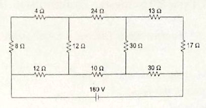
Compute the current in the 8Ω resistor as shown in figure using Superposition Theorem. [Diagram: A DC circuit with a 20V voltage source on the left, a 4Ω resistor in the top left branch, an 8Ω resistor in the central vertical branch, a 4Ω resistor in the top right branch, and a 30V voltage source in the right vertical branch.]
State and explain Thevenin's Theorem.
Using Thevenin's equivalent circuit, find the current through 6 ohm resistor. [Diagram: A DC circuit with an 8V source on the left, a 4Ω resistor in the top left branch, a 10Ω resistor in the middle vertical branch, a 6Ω resistor in the top right branch, and an 8V source in the right vertical branch.]
Answer the following:
A series R-L-C circuit having a resistance of , an inductance of and a capacitance of , is energized from a , , AC supply. Find the— (i) resonant frequency of the circuit; (ii) peak current drawn by the circuit at $50 \text{ Hz}$; (iii) peak current drawn by the circuit at resonant frequency.
A coil of power factor 0.8 is connected in series with a capacitor. The supply frequency is . The potential drop across the coil is found to be equal to the potential drop across the capacitor. Calculate the resistance and inductance of the coil.
Answer the following:
Compare electric and magnetic circuits, clearly stating similarities and dissimilarities between them. State five applications of magnetic circuit in engineering field.
Derive the relationship between line voltage and phase voltage, line current and phase current for a 3-phase delta-connected system.
Answer the following:
What is eddy-current loss? What are the undesirable effects of eddy currents? How can they be minimized? Mention some applications of eddy-currents.
An iron ring of cross-sectional area is wound with a wire of 120 turns and has a cut of . Calculate the magnetizing current required to produce a flux of , if mean length of magnetic path is and relative permeability of iron is 650.
Answer the following:
Define voltage regulation of a transformer and derive conditions for (i) zero regulation and (ii) maximum regulation. Also draw the curve of variation of voltage regulation with power factor.
Derive an expression for the induced e.m.f of a transformer. A , , single-phase transformer is built on a core having an effective cross-sectional area of and has 80 turns in the low-voltage winding. Calculate— (i) the value of the maximum flux density in the core; (ii) the number of turns in the high-voltage winding.
Describe with neat sketches the construction of a 3-phase induction motor. Explain the principle of operation of a 3-phase induction motor. What is meant by slip in an induction motor?
Write short notes on any two of the following :
Components of LT switch gear.
Necessity and Types of Earthing.
Working of MCB & ELCB.
Speed control of DC motor.
Instructions:
- The marks are indicated in the right-hand margin.
- There are NINE questions in this paper.
- Attempt FIVE questions in all.
- Question No. 1 is compulsory
Q.1 Choose the correct answer of the following (any seven):
The maximum power will be transferred from a voltage source to a load when
The unit of magnetic flux density is
The condition for maximum efficiency in a transformer is
If a circuit does not contain any source of energy or emf, it is known as
Which of the following elements of electrical engineering cannot be analysed using Ohm's law?
How many cycles will an AC signal make in 2 seconds if its frequency is 100 Hz?
For domestic wiring purpose, how are circuits connected?
Pure inductive circuit
The time constant for an RL circuit is
Which of the elements in the following is not bilateral?
Q.2 Solve both questions :
Define Q-factor. What is the Q-factor (quality factor) of a series circuit that resonates at 6 kHz, has equal reactance of 4 kilo-ohms each and a resistor value of 50 ohms?
A series R-L-C circuit containing a resistance of $10\,\Omega$, an inductance of 0.45 H and a capacitor of $400\,\mu\mathrm{F}$ is connected in series across a 120 V, 50 Hz supply. Calculate the total circuit impedance, the circuit current, power factor and draw the voltage phasor diagram.
Q.3 Solve both questions :
Explain the procedure of Thevenin's theorem and Norton's theorem to simplify any complex DC Circuit. What are the similarities and dissimilarities between these two theorems?
Explain with proper examples:-
Q.4 Solve both questions :
Explain the working principle and construction of a three phase induction motor. What is meant by slip in an Induction motor?
A 3-Phase, 400 V, 50 Hz, 4-Pole induction motor runs at slip of 0.05. Determine:
Q.5 Solve both questions :
Explain the working of single-phase transformer on no-load condition and draw its phasor diagram.
A 100 kVA transformer is rated 11 kW/230V, 50 Hz. It requires 310V to be applied to the primary to circulate full-load current with short on the secondary side absorbing 5.21 kW. Determine its per cent voltage regulation and the primary voltage for power factors of (i) unity (ii) 0.8 lagging and (iii) 0.8 leading.
Q.6 Solve both questions :
A $4\,\Omega$ resistor is connected to a 10 mH inductor across a 100 V, 50 Hz voltage source. Find the (i) impedance of the circuit (ii) input current (iii) voltage drop across the resistor and inductor (iv) power factor of the circuit (v) real power consumed in the circuit and (vi) total power supplied.
A series RL-C circuit has inductance of 10 mH and resistance of $2\,\Omega$. What is the value of capacitance that will produce resonance? Also find the current at resonance frequency and maximum instantaneous energy stored in the inductance at resonance. Assume the supply as 230 V, 10000 Hz sinusoidal.
Q.7 Solve both questions :
Derive the expressions of equivalent star network resistances from the delta network comprising of $R_{12}, R_{23}, R_{31}$ where nodes are termed as 1, 2, 3 respectively.
Two coils, connected in series-aiding fashion, have a total inductance of 250 mH. When connected in a series-opposing configuration, the coils have a total inductance of 150 mH. If the inductance of one coil ($L_1$) is three times the other, then find $L_1, L_2$ and M. What is the coupling coefficient?
Q.8 Solve both questions :
Compare electric and magnetic circuits, clearly stating similarities and dissimilarities between them. State five applications of magnetic circuit in engineering field.
Draw and explain the B-H curves for air and a magnetic material. What are different types of magnetic losses? How can they be minimized?
Q.9 Write short notes on any two of the following:
Instructions:
- The marks are indicated in the right-hand margin.
- There are NINE questions in this paper.
- Attempt FIVE questions in all.
- Question No. 1 is compulsory
Q.1 Choose the correct answer of the following (any seven):
The maximum power will be transferred from a voltage source to a load when
The unit of magnetic flux density is
The condition for maximum efficiency in a transformer is
If a circuit does not contain any source of energy or emf, it is known as
Which of the following elements of electrical engineering cannot be analysed using Ohm's law?
How many cycles will an AC signal make in 2 seconds if its frequency is 100 Hz?
For domestic wiring purpose, how are circuits connected?
Pure inductive circuit
The time constant for an RL circuit is
Which of the elements in the following is not bilateral?
Q.2 Solve both questions :
Define Q-factor. What is the Q-factor (quality factor) of a series circuit that resonates at 6 kHz, has equal reactance of 4 kilo-ohms each and a resistor value of 50 ohms?
A series R-L-C circuit containing a resistance of , an inductance of 0.45 H and a capacitor of is connected in series across a 120 V, 50 Hz supply. Calculate the total circuit impedance, the circuit current, power factor and draw the voltage phasor diagram.
Q.3 Solve both questions :
Explain the procedure of Thevenin's theorem and Norton's theorem to simplify any complex DC Circuit. What are the similarities and dissimilarities between these two theorems?
Explain with proper examples:-
Q.4 Solve both questions :
Explain the working principle and construction of a three phase induction motor. What is meant by slip in an Induction motor?
A 3-Phase, 400 V, 50 Hz, 4-Pole induction motor runs at slip of 0.05. Determine:
Q.5 Solve both questions :
Explain the working of single-phase transformer on no-load condition and draw its phasor diagram.
A 100 kVA transformer is rated 11 kW/230V, 50 Hz. It requires 310V to be applied to the primary to circulate full-load current with short on the secondary side absorbing 5.21 kW. Determine its per cent voltage regulation and the primary voltage for power factors of (i) unity (ii) 0.8 lagging and (iii) 0.8 leading.
Q.6 Solve both questions :
A resistor is connected to a 10 mH inductor across a 100 V, 50 Hz voltage source. Find the (i) impedance of the circuit (ii) input current (iii) voltage drop across the resistor and inductor (iv) power factor of the circuit (v) real power consumed in the circuit and (vi) total power supplied.
A series RL-C circuit has inductance of 10 mH and resistance of . What is the value of capacitance that will produce resonance? Also find the current at resonance frequency and maximum instantaneous energy stored in the inductance at resonance. Assume the supply as 230 V, 10000 Hz sinusoidal.
Q.7 Solve both questions :
Derive the expressions of equivalent star network resistances from the delta network comprising of where nodes are termed as 1, 2, 3 respectively.
Two coils, connected in series-aiding fashion, have a total inductance of 250 mH. When connected in a series-opposing configuration, the coils have a total inductance of 150 mH. If the inductance of one coil ($L_1$) is three times the other, then find and M. What is the coupling coefficient?
Q.8 Solve both questions :
Compare electric and magnetic circuits, clearly stating similarities and dissimilarities between them. State five applications of magnetic circuit in engineering field.
Draw and explain the B-H curves for air and a magnetic material. What are different types of magnetic losses? How can they be minimized?
Q.9 Write short notes on any two of the following:
Instructions:
- The marks are indicated in the right-hand margin.
- There are NINE questions in this paper.
- Attempt FIVE questions in all.
- Question No. 1 is compulsory.
Q.1 Short answer-type questions (any seven):
State and explain Kirchhoff's laws with an example.
Which winding (LV or HV) should be kept open while conducting OC test? Justify your answer.
Assume that the given transformer has the following name plate ratings: 40 kVA, 440 V/11 kV, 50 Hz. What do these numbers imply?
What is a commutator in d.c. machine?
What is meant by linear network? Explain $R$, $L$ and $C$ as linear elements.
Differentiate among real, reactive and apparent powers.
Calculate maximum value and r.m.s. value of $v = 10 \sin \omega t - 17.3 \cos \omega t$.
A 250 V bulb passes a current of 0.3 A. Calculate the power in the lamp.
Define unilateral and bilateral elements.
Give some applications of three-phase induction motor.
Q.2 Solve both questions :
An a.c. current varying sinusoidal with frequency 50 Hz has r.m.s. value 20 A. Write equation for instantaneous value and find this value 0.0125 seconds after passing through maximum value.
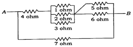
Calculate the resistance between A and B from the figure given below:
Q.3 Solve both questions :
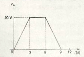
Explain the r.m.s. value. Solve the $V_{\text{rms}}$ value of given waveform in the figure.
Two coils, connected in series-adding fashion, have a total inductance of 250 mH. When connected in a series-opposing configuration, the coils have a total inductance of 150 mH. If the inductance of one coil ($L_1$) is three times the other, then find $L_1, L_2$ and M. What is the coupling coefficient?
Q.4 Solve both questions :
Explain the principle of transformer action.
A series circuit consists of a resistance of $4\,\Omega$, an inductance of 500 mH and a variable capacitance connected across a 100 V, 50 Hz supply. Calculate the capacitance requires for producing a series resonance condition, and the voltages generated across both the inductor and the capacitor at the point of resonance.
Q.5 Solve both questions :
Define parallel resonance. Calculate at resonance the resultant current and quality factor in terms of the parameters of a circuit.
Explain the advantages of rotating field-type alternator.
Q.6 Solve this question :
A 3-phase, 6-pole, star-connected alternator revolves at 1000 r.p.m. The stator has 90 slots and 8 conductors per slot. The flux per pole is 0.05 Wb. Calculate the voltage generated, if $K_w = 0.96$.
Q.7 Solve both questions :
Explain the principle of operation of d.c. motor.
A balanced star-connected load of $(8+j6)\,\Omega$ per phase is connected to a balanced 3-phase, 400 V supply. Find the line current, power factor, power and total volt-amperes.
Q.8 Solve this question :
A 6-pole alternator runs at 1000 r.p.m., and supplies power to a 4-pole, 3-phase induction motor. The frequency of rotor of induction motor is 2 Hz. Determine the slip and speed of the motor.
Q.9 Solve this question :
Two coils, X of 12000 turns and Y of 15000 turns, lie in parallel planes so that 45% of the flux produced by coil X links coil Y. A current of 5 A in X produces 0.05 Wb while the same current in Y produces 0.075 Wb. Calculate (a) the mutual inductance, (b) the coupling coefficient and (c) the percentage of flux produced by coil Y and linking with coil X.
Instructions:
- The marks are indicated in the right-hand margin.
- There are NINE questions in this paper.
- Attempt FIVE questions in all.
- Question No. 1 is compulsory.
Q.1 Short answer-type questions (any seven):
State and explain Kirchhoff's laws with an example.
Which winding (LV or HV) should be kept open while conducting OC test? Justify your answer.
Assume that the given transformer has the following name plate ratings: 40 kVA, 440 V/11 kV, 50 Hz. What do these numbers imply?
What is a commutator in d.c. machine?
What is meant by linear network? Explain $R$, $L$ and $C$ as linear elements.
Differentiate among real, reactive and apparent powers.
Calculate maximum value and r.m.s. value of $v = 10 \sin \omega t - 17.3 \cos \omega t$.
A 250 V bulb passes a current of 0.3 A. Calculate the power in the lamp.
Define unilateral and bilateral elements.
Give some applications of three-phase induction motor.
Q.2 Solve both questions :
An a.c. current varying sinusoidal with frequency 50 Hz has r.m.s. value 20 A. Write equation for instantaneous value and find this value 0.0125 seconds after passing through maximum value.
Calculate the resistance between A and B from the figure given below:

Q.3 Solve both questions :
Explain the r.m.s. value. Solve the $V_{\text{rms}}$ value of given waveform in the figure.

Two coils, connected in series-adding fashion, have a total inductance of 250 mH. When connected in a series-opposing configuration, the coils have a total inductance of 150 mH. If the inductance of one coil ($L_1$) is three times the other, then find $L_1, L_2$ and M. What is the coupling coefficient?
Q.4 Solve both questions :
Explain the principle of transformer action.
A series circuit consists of a resistance of $4\,\Omega$, an inductance of 500 mH and a variable capacitance connected across a 100 V, 50 Hz supply. Calculate the capacitance requires for producing a series resonance condition, and the voltages generated across both the inductor and the capacitor at the point of resonance.
Q.5 Solve both questions :
Define parallel resonance. Calculate at resonance the resultant current and quality factor in terms of the parameters of a circuit.
Explain the advantages of rotating field-type alternator.
Q.6 Solve this question :
A 3-phase, 6-pole, star-connected alternator revolves at 1000 r.p.m. The stator has 90 slots and 8 conductors per slot. The flux per pole is 0.05 Wb. Calculate the voltage generated, if $K_w = 0.96$.
Q.7 Solve both questions :
Explain the principle of operation of d.c. motor.
A balanced star-connected load of $(8+j6)\,\Omega$ per phase is connected to a balanced 3-phase, 400 V supply. Find the line current, power factor, power and total volt-amperes.
Q.8 Solve this question :
A 6-pole alternator runs at 1000 r.p.m., and supplies power to a 4-pole, 3-phase induction motor. The frequency of rotor of induction motor is 2 Hz. Determine the slip and speed of the motor.
Q.9 Solve this question :
Two coils, X of 12000 turns and Y of 15000 turns, lie in parallel planes so that 45% of the flux produced by coil X links coil Y. A current of 5 A in X produces 0.05 Wb while the same current in Y produces 0.075 Wb. Calculate (a) the mutual inductance, (b) the coupling coefficient and (c) the percentage of flux produced by coil Y and linking with coil X.
Instructions:
- The marks are indicated in the right-hand margin.
- There are NINE questions in this paper.
- Attempt FIVE questions in all.
- Question No. 1 is compulsory.
Q.1 Choose the correct alternative (any seven):
In an AC series R-L-C circuit, the voltage across R and L is 20 V, voltage across L and C is 9 V and voltage across R-L-C is 15 V. What is the voltage across C?
The salient type of alternator is used in which of the following power stations?
A single-phase AC voltage source has 200 V r.m.s. and is connected to a system which consumes an active power of 300 W. What is the reactive power consumed by the system, if 2.5 A r.m.s. current is drawn?
The maximum power will be transferred from a voltage source to a load when
The condition for maximum efficiency in a transformer is
The unit of magnetic flux density is
The supply frequency of a transformer is increased, the rating of the transformer would have been
A series circuit contains a resistance of $4\,\Omega$ and inductance of 0.5H and a variable capacitor across a 100V, 50Hz supply. What would be the voltage across an inductor?
In an induction motor, if the air gap increased
The pole of DC machine is laminated to
Q.2 Solve all parts :
A coil wire when connected to a DC supply of 100V takes a current of 10A. When it connected to an AC supply of 100V at a frequency of 50Hz, the current is 5A. Explain the difference and calculate the coefficient of self-inductance of the coil.
The current in a circuit is given by $(4.5+j12)\,\mathrm{A}$ when the applied voltage is $(100+j150)\,\mathrm{V}$. Determine (i) the complex expression for the impedance stating whether it is inductive or capacitive, (ii) the power and (iii) the phase angle between the current and voltage.
What is meant by the Q-factor of a series coil and what is the significance?
Q.3 Solve all parts :
If a coil of unknown resistance and reactance is connected in series with a 100 V, 50 Hz supply, the current locus diagram is found to have a diameter of 5 A and when the value of series resistor is 15 Ω, the power dissipated is maximum. Calculate the reactance and resistance of the coil and the value of maximum power in the circuit and the maximum current.
Three similar coils, each of resistance 20 Ω and inductance 0.5 H are connected in (i) star and (ii) delta to a 3-φ, 50 Hz, 400 V supply. Calculate the line current and the total power consumed.
The admittance of a circuit is 0.03 - j0.04 mho. Find the values of the resistance and inductive reactance of the circuit, if they are joined (i) in series and (ii) in parallel.
Q.4 Solve all parts :
Describe the properties of zinc chloride and mercury battery cell types.
Describe the properties of fuse and its limitations.
What are various factors to be considered for the calculations of energy consumption?
Q.5 Solve all parts :
When a transformer is connected to a 1000 V, 50 Hz supply, the core loss is 1000 W of which 650 is hysteresis and 350 is eddy current loss. If the applied voltage is raised to 2000 V and frequency to 100 Hz, what could be the new core losses?
Explain the star-delta connection of three-phase transformer by assuming step-down mode. Draw the phasor diagram of line and phase voltages.
The primary resistance of a transformer is 0.1 Ω and its leakage reactance is 0.8 Ω. When the applied voltage is 1000 V, the primary current is 50 A at a lagging power factor of 0.6. Find the primary induced e.m.f.
Q.6 Solve all parts :
Derive the e.m.f. equation of a DC generator.
A 6 pole, 40 Hz, three-phase induction motor running on full-load with 4% slip develops a torque of 149.3 N·m at its shaft. The friction and windage losses are 200 W and the stator core and copper losses are 1620 W. Calculate— (i) the total output power; (ii) the rotor copper losses; (iii) the efficiency at full load.
Explain the speed control of separately excited DC motor above and below its rated speed.
Q.7 Solve all parts :
What is the necessity of damper winding in an alternator? Describe the constructional details of the damper winding.
Is it possible for the rotor to run at synchronous speed? Explain your answer.
Compare the lap winding and wave winding of a DC motor.
Derive an expression for the torque developed by DC motor.
Q.8 Solve all parts :
An iron ring, cross-sectional area of 5 $\mathrm{cm^2}$ and mean length of 100 cm, has an air gap of 2 mm cut in it. Three separate coils having 100, 200 and 300 turns are wound on the ring and carry currents of 1 A, 2.5 A and 3 A, respectively such that they produce additive fluxes in the ring. Relative permeability of the ring material is 1000. Calculate the flux in the air gap.
Explain the nature and direction of force between two parallel current-carrying conductors.
A conductor of length 10 cm carrying 5 A is placed in a uniform magnetic field of flux density 1.25 tesla. Find the force acting on the conductor, if it is placed (i) along the lines of magnetic flux and (ii) perpendicular to the lines of flux.
Q.9 Solve both questions :
A resistance of 10 Ω is connected in series with the two resistances each of 15 Ω arranged in parallel. What resistance must be shunted across this parallel combination so that the total current taken will be 1.5 A from 20 V applied?
State and explain the procedure of Thevenin's theorem and Norton's theorem.
Instructions:
- The marks are indicated in the right-hand margin.
- There are NINE questions in this paper.
- Attempt FIVE questions in all.
- Question No. 1 is compulsory.
Q.1 Choose the correct answer of the following (any seven):
Lamps in street lighting are all connected in
The rotor slots in a 3-phase induction motor are kept inclined. This phenomenon is known as
An alternator with higher value of SCR has
If the flux of a DC motor approaches zero, its speed will
The core flux of a practical transformer with a resistive load
A transformer has a percentage resistance of 2% and percentage reactance of 4%. What are its voltage regulations at 0.8 lagging and 0.8 leading respectively?
Higher the Q of a series circuit, narrower its
A 10 mH inductor carries a sinusoidal current of 1A r.m.s. at a frequency of 50 Hz. The average power dissipated by the inductor is
Which of the following statements is incorrect?
Which of the following is not bilateral element?
Q.2 Solve all parts :
Find the current through each resistor of the following circuit using nodal analysis:
Explain the concept of superposition theorem applied to the electric circuit by taking a 3-element T-network and two batteries.
Find the equivalent resistance between points A and B in the following circuit:
Q.3 Solve all parts :
An iron cored coil draws 2A at 0.5 p.f. lag against a 50 Hz, 100 V supply. Iron core being then removed, the voltage applied being 50 V, the current rises to 5A at 0.78 lag. Find the inductance of each case.
A resistance of $10\,\Omega$, an inductance of 150 mH and a capacitor of $100\,\mu\mathrm{F}$ are connected across a 50 V, 50 Hz source. Find the branch currents and total current. Draw the phasor diagram.
Discuss the effect of resistance of RLC series circuit on the frequency response curve.
Q.4 Solve all parts :
An iron ring 8 cm mean diameter is made up of round iron diameter 1 cm and permeability of 900 has an air gap of 2 mm wide. It consists of winding with 400 turns carrying a current of 3.5 A. Determine— (i) MMF; (ii) total reluctance; (iii) the flux; (iv) flux density in ring.
Give the comparison between electric circuit and magnetic circuit.
Explain the experimental method of obtaining hysteresis loop of magnetic circuit.
Q.5 Solve all parts :
The open-circuit and short-circuit tests on a 10 kVA, 125/250 V, 50 Hz single-phase transformer
gave the following results:
OC test : 125 V, 0.6 A, 50 W on LV side
SC test : 15 V,
30
A, 100 W
on HV side
Calculate (i) copper loss on full load, (ii) full-load efficiency at 0.8
leading
p.f., (iii) half-load efficiency at 0.8 leading p.f. and (iv) voltage regulation at full load,
0.9 leading p.f.
Explain the various three-phase transformer connections with neat circuit and phasor diagrams.
Q.6 Solve all parts :
Draw the speed-torque characteristics of DC shunt motors and series motors.
Explain the constructional details of alternators.
The lap wound armature of a 4-pole DC shunt motor has 600 armature turns and it takes 100 Amps when running at 600 r.p.m. The flux per pole is 100 mWb. Calculate the gross mechanical torque developed and the net power output if the torque lost in friction, windage and core losses is 60 N-m.
Q.7 Solve all parts :
A 4-pole, 50 Hz, 3-phase induction motor running on full load develops a useful torque of 200 N-m when the rotor e.m.f. makes 120 complete cycles per minute. If the mechanical torque lost in friction and rotor core loss is 15 N-m, calculate the— (i) shaft power output; (ii) rotor copper losses; (iii) stator input; (iv) motor efficiency.
Differentiate the principle of operation of induction and synchronous motors.
Draw the speed-torque characteristics of an induction motor.
List the various types of DC generators and draw their electrical circuits.
Q.8 Solve all parts :
Define cold ranking ampere and specific power in batteries.
Describe the various devices used to improve the system power factor.
Explain the various types of earthing systems.
Q.9 Solve both questions :
Explain maximum power transfer theorem applied in a DC network.
Why a DC series motor cannot be started on no load? Explain your answer with the help of basic speed-torque equation and necessary diagrams.
Instructions:
- The marks are indicated in the right-hand margin.
- There are NINE questions in this paper.
- Attempt FIVE questions in all.
- Question No. 1 is compulsory.
Q.1 Choose the correct answer of the following (any seven):
Lamps in street lighting are all connected in
The rotor slots in a 3-phase induction motor are kept inclined. This phenomenon is known as
An alternator with higher value of SCR has
If the flux of a DC motor approaches zero, its speed will
The core flux of a practical transformer with a resistive load
A transformer has a percentage resistance of 2% and percentage reactance of 4%. What are its voltage regulations at 0.8 lagging and 0.8 leading respectively?
Higher the Q of a series circuit, narrower its
A 10 mH inductor carries a sinusoidal current of 1A r.m.s. at a frequency of 50 Hz. The average power dissipated by the inductor is
Which of the following statements is incorrect?
Which of the following is not bilateral element?
Q.2 Solve all parts :
Find the current through each resistor of the following circuit using nodal analysis:

Explain the concept of superposition theorem applied to the electric circuit by taking a 3-element T-network and two batteries.
Find the equivalent resistance between points A and B in the following circuit:

Q.3 Solve all parts :
An iron cored coil draws 2A at 0.5 p.f. lag against a 50 Hz, 100 V supply. Iron core being then removed, the voltage applied being 50 V, the current rises to 5A at 0.78 lag. Find the inductance of each case.
A resistance of $10\,\Omega$, an inductance of 150 mH and a capacitor of $100\,\mu\mathrm{F}$ are connected across a 50 V, 50 Hz source. Find the branch currents and total current. Draw the phasor diagram.
Discuss the effect of resistance of RLC series circuit on the frequency response curve.
Q.4 Solve all parts :
An iron ring 8 cm mean diameter is made up of round iron diameter 1 cm and permeability of 900 has an air gap of 2 mm wide. It consists of winding with 400 turns carrying a current of 3.5 A. Determine— (i) MMF; (ii) total reluctance; (iii) the flux; (iv) flux density in ring.
Give the comparison between electric circuit and magnetic circuit.
Explain the experimental method of obtaining hysteresis loop of magnetic circuit.
Q.5 Solve all parts :
The open-circuit and short-circuit tests on a 10 kVA, 125/250 V, 50 Hz single-phase transformer
gave the following results:
OC test : 125 V, 0.6 A, 50 W on LV side
SC test : 15 V,
30
A, 100 W
on HV side
Calculate (i) copper loss on full load, (ii) full-load efficiency at 0.8
leading
p.f., (iii) half-load efficiency at 0.8 leading p.f. and (iv) voltage regulation at full load,
0.9 leading p.f.
Explain the various three-phase transformer connections with neat circuit and phasor diagrams.
Q.6 Solve all parts :
Draw the speed-torque characteristics of DC shunt motors and series motors.
Explain the constructional details of alternators.
The lap wound armature of a 4-pole DC shunt motor has 600 armature turns and it takes 100 Amps when running at 600 r.p.m. The flux per pole is 100 mWb. Calculate the gross mechanical torque developed and the net power output if the torque lost in friction, windage and core losses is 60 N-m.
Q.7 Solve all parts :
A 4-pole, 50 Hz, 3-phase induction motor running on full load develops a useful torque of 200 N-m when the rotor e.m.f. makes 120 complete cycles per minute. If the mechanical torque lost in friction and rotor core loss is 15 N-m, calculate the— (i) shaft power output; (ii) rotor copper losses; (iii) stator input; (iv) motor efficiency.
Differentiate the principle of operation of induction and synchronous motors.
Draw the speed-torque characteristics of an induction motor.
List the various types of DC generators and draw their electrical circuits.
Q.8 Solve all parts :
Define cold ranking ampere and specific power in batteries.
Describe the various devices used to improve the system power factor.
Explain the various types of earthing systems.
Q.9 Solve both questions :
Explain maximum power transfer theorem applied in a DC network.
Why a DC series motor cannot be started on no load? Explain your answer with the help of basic speed-torque equation and necessary diagrams.
Instructions:
- The marks are indicated in the right-hand margin.
- There are NINE questions in this paper.
- Attempt FIVE questions in all.
- Question No. 1 is compulsory.
Section A
Choose the correct alternative from any seven of the following :
The full-load copper loss and iron loss of a transformer are and respectively. The copper loss and iron loss at half load will be respectively:
In a transformer with 2000 turns on the HV side, the open circuit test result gives on LV side. The core-loss component of current is approximately:
A 4-pole d.c. generator is running at at no load, the frequency of current in the armature winding is:
What is the load at which maximum efficiency occurs in case of a transformer with iron loss of and full-load copper loss of ?
In two-wattmeter method of power measurement, if both the wattmeters show positive and equal readings, then it can be concluded that the load:
Which among these is the least expensive protection for over current in low voltage system?
A circuit breaker is:
Which three-phase connection is used to in a transformer to introduce a phase difference of between its output and corresponding input line voltage?
Two transformers operating in parallel will share the load depending upon their:
A d.c. shunt generator is supplying a load of at . Its armature and filed resistances are and respectively. What is the generated e.m.f.?
Section B
Answer the following:
Open and short circuit tests performed on a transformer yielded the following data : No-load loss = , Full-load short circuit loss = . Calculate the load at which the transformer efficiency would be maximum for a given power factor. Calculate the efficiency for a p.f. of .
Draw the neat and exact phasor diagram of the 1-$\phi$ transformer on load condition.
Answer the following:
A 3-$\phi$, 4-pole , star-connected induction motor running on full-load develops a useful torque of . The rotor e.m.f. is completing 120 cycles per minute. If torque lost in friction is , calculate— (i) slip; (ii) net output power; (iii) rotor copper losses/phase; (iv) rotor resistance per phase if rotor current is in running condition.
Explain the characteristics (i) T vs. Ia, (ii) N vs. Ia and (iii) N vs. T of DC shunt motor.
Answer the following:
A d.c. shunt motor has a shunt resistance of and an armature resistance of . For a given load, motor runs at drawing a current of from the supply. If a resistance of is added in series with the field winding, find the new armature current and the speed. Assume load torque constant and magnetization curve to be linear.
Draw the speed torque characteristics of (i) DC series motor, (ii) DC shunt motor and (iii) DC differentially compound motor.
Answer the following:
Find the current in the following circuit by applying Thevenin’s theorem : [Diagram: A bridge circuit. Voltage source on left, on right. Resistors (A-B), (B-C), (C-D), (B-G), (C-F). Terminals H, G, F, E on bottom wire. through , through , through .]
Determine the resistance between the terminals A and B in the circuit below : [Diagram: A bridge circuit. Node A at top, node B at bottom. Resistors in upper delta. in middle branches. in lower branches. vertical resistor in the center.]
Answer the following:
Explain the AC circuits containing only inductance and capacitance clearly with equations.
A three-phase balanced delta-connected load of is connected across a , 3-$\phi$ balanced supply. Determine the phase currents, line currents and power drawn by the load. Assume the phase sequence to be RYB.
Answer the following:
Write the comparison between electric circuits and magnetic circuits.
What do you understand from the following terms? (i) Silicon steel (ii) Magnetostriction (iii) Statically induced e.m.f. (iv) Dynamically induced e.m.f.
Answer the following:
What do you understand by earthing? Explain a single-phase a.c. circuit connection with earthing.
Explain the procedure to improve the power factor in a.c. circuits.
Answer the following:
What are the various DC motors available based on the excitation? Draw their equivalent circuit.
A single-phase transformer with a ratio of takes a no-load current of at lagging. If the secondary supplies a current of at a p.f. of lagging, estimate the current taken by the primary and draw the phasor diagram.
Instructions:
- The marks are indicated in the right-hand margin.
- There are EIGHT questions in this paper.
- Attempt FIVE questions in all.
- Question No. 1 is compulsory.
Section A
Answer any seven short answer-type questions :
Define active and passive element.
State and explain Norton theorem.
A half-cycle average voltage of is equal to what r.m.s. voltage?
What are the phase voltage and phase current of three-phase delta-connected system?
Draw equivalent circuit of a DC motor. [Diagram: Equivalent circuit of a DC motor.]
What is resonance?
Relate flux, reluctance and permeability.
Define power factor.
Write the application of Ohm's law.
Describe important characteristic of an inductor.
Section B
Answer the following:
Define Q-factor. What is the (quality factor) of a series circuit that resonates at , has equal reactance of each and a resistor value of ?
A series R-L-C circuit containing a resistance of , an inductance of and a capacitor of is connected in series across a , supply. Calculate the total circuit impedance, the circuit current, power factor and draw the voltage phasor diagram.
Answer the following:
Find the resistor value in the Fig. 1 shown below : [Diagram: Fig. 1. A circuit with a 10A current source on the left, 5A current source on the right. and sources. Resistors , , , and in a bridge/ladder configuration.]
In a balance 3-phase circuit, . When power is measured by two-wattmeter method, one meter reads and other zero. What is the power factor of load? If unity power factor and line current are same, what would be the reading of each wattmeter?
Answer the following:
What are the two general types of transformer? Why is the low-voltage winding placed near the core? What will be the output of transformer if it is operated on DC supply?
Describe the operation of a single-phase transformer, explaining clearly the function of different parts. Why are the cores laminated?
Draw and explain the B-H curves for air and a magnetic material. What are different types of magnetic losses? How can they be minimized?
What is circuit? What is the difference between fuse and circuit breaker? Explain the objective of earthing.
Write Thevenin theorem statement. Determine the equivalent Thevenin's circuit between terminals a and b in the circuit shown in Fig. 2 below. Resistances are in ohms : [Diagram: Fig. 2. A bridge circuit with a 50V source on the left. Resistors 10Ω and 15Ω in the upper branches, 6Ω and 8Ω in the lower branches. Terminal 'a' is between 10Ω and 6Ω. Terminal 'b' is between 15Ω and 8Ω. A 5Ω resistor is connected between a and b.]
Describe with neat sketches the construction of a 3-phase induction motor. Explain the principle of operation of a 3-phase induction motor. What is meant by slip in an induction motor?
Instructions:
- The marks are indicated in the right-hand margin.
- There are NINE questions in this paper.
- Attempt FIVE questions in all.
- Question No. 1 is compulsory.
Section A
Choose the correct alternative from any seven of the following :
The current through resistor is: [Diagram: A circuit with a resistor in series with a source. Then a parallel branch with a resistor and a current source. Then a resistor and a dependent voltage source. is the voltage across the resistor.]
A , 3-phase induction motor has an output of and operates at a power factor of lagging with an efficiency of . The readings of the two wattmeters respectively are:
A coil takes when connected across , mains. The power consumed by the coil is found to be . The coil inductance and power factor respectively are:
Which among the following is/are the main characteristic(s) of a fuse element?
A resistance, a condenser and a variable inductance are connected in series across a , supply. The maximum current which can be obtained by varying the inductance under resonance is and the voltage across the condenser is then . The values of R-L-C respectively are:
Three similar coils, each of resistance and inductance of , are connected in delta to a 3-phase, , supply. The line current and total powers absorbed respectively are:
A 440/110 transformer has an effective primary resistance of and secondary resistance of . Its iron losses at normal input are . What would be the secondary current at which the maximum efficiency will occur?
For high current and low voltage rating, which winding is employed to DC machine?
When the mechanical power developed by a DC motor is maximum:
In two-wattmeter method of power measurement, if one of the wattmeters gives negative reading, then it can be concluded that the load:
Section B
Answer the following:
The efficiency of a , , , single-phase transformer is at half full-load at leading and at full-load upf. Determine— (i) iron-loss; (ii) full-load copper loss; (iii) maximum efficiency at upf; (iv) kVA at which maximum efficiency occurs.
In a , transformer, the total iron loss is . When the applied voltage is at , the corresponding loss is . Calculate the eddy-current loss at normal frequency and voltage.
Answer the following:
A 3-$\phi$, 4-pole, , star-connected induction motor running on full-load develops a useful torque of . The rotor EMF is completing 120 cycles per minute. If torque lost in friction is , calculate— (i) slip; (ii) net output power; (iii) mechanical power developed; (iv) rotor copper losses/phase; (v) rotor efficiency; (vi) rotor resistance per phase if rotor current is in running condition.
Explain the torque speed characteristics of 3-phase induction motor by considering the zones of operation.
Answer the following:
A , 3-$\phi$, 8-pole, , , star-connected induction motor has the following parameters : Stator resistance = , Stator reactance = , Equivalent rotor resistance referred to stator = , Equivalent rotor reactance referred to stator = . The stator core loss is while mechanical loss is . It draws a no-load current of at a pf of lagging. While at a speed of , calculate— (i) input line current and pf; (ii) torque developed; (iii) mechanical power developed; (iv) efficiency. Use approximate equivalent circuit.
Explain the operating principle of alternator.
Answer the following:
Find the value of R such that would flow in it for the network shown in the following figure : [Diagram: A bridge/ladder circuit. On the left, a resistor in parallel with a branch containing a resistor and a battery. Then a top branch with resistor R. Then a parallel branch with a resistor and a resistor on the right.]
Find the resistance between terminals x and y from the following figure : [Diagram: A complex bridge circuit with resistors and inner resistors .]
Answer the following:
A inductor is connected in series with a sinusoidal supply. Find peak, RMS and average values of current and power consumed.
Explain the effect of power factor on two wattmeter readings in a two-wattmeter method of power measurement.
Answer the following:
A steel ring has a diameter of , a cross-section of and radial air-gap of cut across it. When excited by a current of through a coil of 1000 turns wound on the ring core, it produces an air-gap flux of . Neglecting leakage and fringing, calculate (i) relative permeability of steel and (ii) total reluctance of the magnetic circuit.
What are the various ferromagnetic materials? Write their applications and properties.
Explain the terms 'fringing' and 'leakage flux'.
Answer the following:
Describe the various types of batteries.
Define the following terms : (i) Switch fuse unit (ii) MCB (iii) ELCB (iv) MCCB.
Answer the following:
What value of equivalent resistance exists between points A and B? [Diagram: A large resistor network. Top branch A-B has resistors . Vertical branches have . Horizontal internal branches have . Bottom branch has .]
Draw the resonance curve for a series resonance circuit and compare with it a parallel resonance.
Instructions:
- The marks are indicated in the right-hand margin.
- There are NINE questions in this paper.
- Attempt FIVE questions in all.
- Question No. 1 is compulsory.
Section A
Attempt any seven short answer-type questions:
Draw the V-I characteristics of ideal and practical current source and voltage source.
State the maximum power transfer theorem.
A sinusoidal voltage of 50 Hz has a maximum value of volts. At what time measured from a positive maximum value will the instantaneous voltage be 141.4 volts?
What are the advantages of three-phase system?
In two-wattmeter method, what will be the power factor when both wattmeters show equal readings?
Explain magnetic leakage and fringing.
How do the hysteresis and eddy current loss depend on frequency?
Define form factor and peak factor.
Write the statement of KVL and KCL.
What is the meaning of phase sequence? How can it be changed?
Section B
Answer the following:
A series circuit having a resistance of , an inductance of and a capacitance of , is energized from a , , AC supply. Find the— (i) resonant frequency of the circuit; (ii) peak current drawn by the circuit at $50 \text{ Hz}$; (iii) peak current drawn by the circuit at resonant frequency.
A coil of p.f. 0.8 is connected in series with a capacitor. The supply frequency is . The potential drop across the coil is found to be equal to the potential drop across the capacitor. Calculate the resistance and inductance of the coil.
Answer the following:
Show that the average power demand, in purely inductive and purely capacitive AC circuit is zero.
In a 3-phase circuit, two wattmeters used to measure power indicate 1000 W and 500 W respectively. Find the power factor of the circuit— (i) when both wattmeter readings are positive; (ii) when the latter reading is obtained by reversing the current coil connections.
Answer the following:
Explain the various losses in a transformer. In which part these losses occur? How to minimize them? On which factors they depend?
Explain the construction and working of a single-phase dynamometer-type wattmeter.
Compare electric and magnetic circuits, clearly stating similarities and dissimilarities between them. State five applications of magnetic circuit in engineering field.
Derive the relationship between line voltage and phase voltage, line current and phase current for a 3-phase delta-connected system.
Determine current in 10 ohm resistance using Norton's theorem in the network as shown in the figure below : [Diagram: A multi-loop DC circuit with two voltage sources (15V and 30V) and resistors (8Ω, 6Ω, 4Ω, 10Ω).]
An iron ring of cross-sectional area is wound with a wire of 100 turns and has a cut of . Calculate the magnetizing current required to produce a flux of if mean length of magnetic path is and relative permeability of iron is 470.
Answer the following:
Derive the expressions of equivalent star network resistances from the delta network comprising of , , , where nodes are termed as 1, 2, 3 respectively.
Draw B-H curve with neat and labelled diagram. Explain its applicability in transformer.
Instructions:
- The marks are indicated in the right-hand margin.
- There are NINE questions in this paper.
- Attempt FIVE questions in all.
- Question No. 1 is compulsory.
Section A
Choose the correct answer of the following (any seven) :
A star-connected network which is equivalent to the delta network is shown in the figure given below. The , and (in ohm) are respectively [Diagram: Star network with R1=3Ω, R2=6Ω, R3=9Ω and equivalent Delta network with RA, RB, RC.]
Superposition theorem is not applicable for
Nodal analysis is based on
The r.m.s. value of sine wave is 100 A. Its peak is
A voltage is represented by a sine wave and has a maximum value of 100 V. Its r.m.s. and average value are respectively
An a.c. source of 200 V r.m.s. supplies active power of 600 W and reactive power of 800 VAR. The r.m.s. current drawn from the source is
The hysteresis and eddy current losses of a 1-$\phi$ transformer working on 200 V, 50 Hz supply are and respectively. The percentage decrease in these losses when operated at 160 V, 40 Hz supply are respectively
The resistance between the terminals a-b, in the network shown in the figure given below, is [Diagram: A bridge-like resistor network with values 3Ω, 5Ω, 4Ω, 6Ω.]
The average value of a sinusoidal waveform for complete cycle ($v_{av}$) is
In a three-phase system, voltages differ in phase by
Section B
Answer the following:
State and explain maximum power transfer theorem.
Find the value of resistance in the figure given below for maximum power transfer and calculate maximum power : [Diagram: A DC circuit with a 5V source, 1A current source, and resistors 1Ω, 10Ω, 2Ω, 3Ω, 5Ω, RL.]
Answer the following:
Define r.m.s. value and average value of sinusoidal waveform.
An RLC series circuit with a resistance of , a inductance of and a capacitance of is supplied with a 100 V supply at variable frequency. Find the following with respect to the series resonant circuit: (i) Frequency of which resonance takes place (ii) Current (iii) Power (iv) Power factor (v) Voltage across RLC at that time (vi) Quality factor (vii) Half-power points
Answer the following:
Define the following : (i) Peak factor (ii) Form factor
The output voltage of an electronic device is given in the following figure : [Diagram: A periodic waveform with peak 15V.] Determine (i) the average value and (ii) the r.m.s. value of the voltage.
Answer the following:
State and explain Thevenin's theorem.
Find the current through resistor in the following figure by Thevenin's theorem : [Diagram: A complex DC circuit with 15V and 10V sources and several resistors.]
In the circuit of figure given below, a 400 V, 50 Hz, 3-phase supply of phase sequence ABC is supplied to a delta-connected load consisting a resistor between lines A and B, a 378 mH inductor between lines B and C, and a 37.8 $\mu$F capacitor between lines C and A. Determine phase and line currents. [Diagram: 3-phase delta-connected load with R, L, and C components.]
Answer the following:
Explain B-H curve with neat diagram.
A coil of 200 turns is wound uniformly over a wooden rim having a mean circumference of 60 cm and uniform cross-sectional area of . If the current through the coil is 4 A, calculate (i) the magnetomotive force, (ii) the total flux and (iii) the flux density.
Answer the following:
What are the different types of moving-coil instrument? Explain any one in detail.
What are the different types of controlling torque? Explain any one in detail.
Write short notes on any two of the following : (a) Star-delta conversion (b) Superposition theorem (c) Moving-iron instruments
Instructions:
- The marks are indicated in the right-hand margin.
- There are NINE questions in this paper.
- Attempt FIVE questions in all.
- Question No. 1 is compulsory.
Section A
Answer any seven short answer-type questions :
Introduce resistance, inductance and capacitance.
State superposition theorem.
A sinusoidal voltage of 60 Hz has a maximum value of volts. At what time measured from a positive maximum value will the instantaneous voltage be 100 volts?
What are the two main advantages of DC excitation system?
In two-wattmeter method, what will be the power factor when both wattmeters show 50 watts readings?
Explain power triangle.
How do hysteresis and eddy current loss depend on frequency?
Define average value and RMS value.
Explain generation of rotating magnetic field in electrical machine.
Differentiate among neutral, grounding and earthing.
Section B
Answer the following:
Find to have maximum power transfer in the circuit shown in Fig. 1. Also obtain the amount of maximum power : [Diagram: Fig 1. A circuit with a 2A current source, resistors of 10Ω, 5Ω, 2Ω, voltage sources of 6V and 10V, and a load resistor R.]
A coil having resistance of and inductance of is switched on to a direct voltage of . Calculate the rate of change of the current (i) at the instant of closing the switch and (ii) when . Also find the steady-state value of the current.
Answer the following:
What is the phase relationship between R, L and C components in a series AC circuit? What are active power, reactive power and apparent power?
On a power distribution system, three loads run in parallel : Load A : 100 VA, 0.5 pf (lag); Load B : 150 W, 0.8 pf (lead); Load C : 200 VA, 100 var (lag). Find the net power position.
Answer the following:
What is eddy-current loss? What are the undesirable effects of eddy currents? How can they be minimized? Mention some applications of eddy-currents.
An iron ring of cross-sectional area is wound with a wire of 120 turns and has a cut of . Calculate the magnetizing current required to produce a flux of , if mean length of magnetic path is and relative permeability of iron is 650.
Answer the following:
Define voltage regulation of a transformer and derive conditions for (i) zero regulation and (ii) maximum regulation. Also draw the curve of variation of voltage regulation with power factor.
Derive an expression for the induced e.m.f. of a transformer. A 3000/200 V, 50 Hz, single-phase transformer is built on a core having an effective cross-sectional area of and has 80 turns in the low-voltage winding. Calculate— (i) the value of the maximum flux density in the core; (ii) the number of turns in the high-voltage winding.
The circuit shown in Fig. 2(i) is the Thevenin equivalent circuit of the circuit shown in Fig. 2(ii). Find the value of the open circuit voltage, and Thevenin resistance, . [Diagram: Fig 2(i) Thevenin equivalent. Fig 2(ii) A circuit with 2A source, 2V source and resistors 3Ω, 6Ω, 6Ω.]
Determine current in resistance using Norton's theorem in the network shown in Fig. 3 : [Diagram: Fig 3. A multi-loop DC circuit with 15V and 35V sources and resistors 10Ω, 5Ω, 8Ω, 12Ω.]
A 100 MVA Y-connected 13.2 kV synchronous generator is connected to a 13.2/132 kV, 100 MVA delta-star transformer. The generators are , , on a 100 MVA base, while transformer reactance is on the same base. The machine is operating on no load, at rated voltage when a three-phase fault occurs at the HT terminals of transformer. Determine— (a) the sub-transient, transient and steady-state symmetrical fault currents in pu and amperes; (b) the maximum possible DC component; (c) the maximum value of instantaneous current.
Answer the following:
Derive the expressions of equivalent star network resistances from the delta network comprising of , , , where nodes are termed as 1, 2, 3 respectively.
What is the main purpose of providing taps in transformer? Suggest the addition in a simplified transformer model when it is used for tap changing transformer.
Instructions:
- The marks are indicated in the right-hand margin.
- There are NINE questions in this paper.
- Attempt FIVE questions in all.
- Question No. 1 is compulsory.
Section A
Write short notes on any seven of the following terms :
Linear elements
Magnetic coupling
Ohm's law
Node and mesh analysis
Q-factor
Bilateral elements
Dependent sources
Current and voltage measurement
Peak factor of sine wave
Behaviour of inductance in DC circuit
Section B
Answer the following:
What is the magnitude of the current drained from the 10 volts source in Fig. 1? [Diagram: Fig. 1. DC circuit with a 2 A current source, a 6 V voltage source, a 10 V voltage source, and resistors 10 Ω, 5 Ω, 2 Ω, and a load R between terminals x and y.]
With reference to Fig. 2 below, determine the voltage appearing across terminals y-z, if a d.c. voltage of 100 volts is applied across x-y. [Diagram: Fig. 2. A resistor network with 100 V across x-y. Labeled resistors: 1 Ω, 2 Ω, 5 Ω, 10 Ω, and 50 Ω. Terminals x, y, z marked.]
Answer the following:
In the circuit given in Fig. 3, find the power loss in the resistor by Thevenin's theorem : [Diagram: Fig. 3. DC circuit with a 2 A current source, a 10 V voltage source, and resistors 10 Ω, 5 Ω, and 1 Ω. Terminals x and y are at the 1 Ω resistor.]
Find Norton's equivalent to the right of a-b terminals in Fig. 4 : [Diagram: Fig. 4. DC circuit with a 3 V voltage source, a 1 A current source, and resistors 10 Ω and 5 Ω. Terminals a and b are at the output.]
Answer the following:
Find in the circuit shown in Fig. 5 : [Diagram: Fig. 5. DC circuit with a 1 A current source, a 1 V voltage source, and resistors 1 Ω, 1 Ω, 2 Ω, and 3 Ω. Loop currents and I are marked.]
Find to have maximum power transfer in the circuit of Fig. 6. Also obtain the amount of maximum power. [Diagram: Fig. 6. Identical to Fig. 1. DC circuit with a 2 A current source, a 6 V voltage source, a 10 V voltage source, and resistors 10 Ω, 5 Ω, 2 Ω, and a load R.]
Answer the following:
A resistor is connected to a 10 mH inductor across a 100 V, 50 Hz voltage source. Find the (i) impedance of the circuit, (ii) input current, (iii) drop across the resistor and inductor, (iv) power factor of the circuit, (v) real power consumed in the circuit and (vi) total power supplied.
A series R$-$L$-$C circuit has inductance of 10 mH and resistance of . What is the value of capacitance that will produce resonance? Also find the current at resonance frequency and maximum instantaneous energy stored in the inductance at resonance. Assume the supply as 230 V, 10000 Hz sinusoidal.
Answer the following:
A 3-phase balanced system supplies 110 volts to a delta-connected load whose phase impedances are equal to (3.54 + j3.54) . Determine the line currents and draw the phasor diagram.
Three identical impedances ($R + jX_L$) are connected in the form of a star against a 415 V (line-line) 3-phase voltage source and drawing a total power of 1.8 kW. Obtain the resistive and reactive components of each phase impedance. Assume the line current to be 10 A.
Answer the following:
Where and how an ammeter or a voltmeter is connected in a circuit? Discuss two methods for current measurement and two methods for voltage measurement.
Discuss about a suitable AC power measurement device with neat diagram and clear nomenclature.
Derive the mathematical expression of total inductance in series-connected coupled coils— (a) when flux of both the coils are mutually assisting; (b) when flux of both the coils are mutually opposing.
Find the total inductance of the three series-connected coupled coils for the circuit shown in Fig. 7 : [Diagram: Fig. 7. Three coupled coils L1, L2, L3 in series. Mutual inductances M12, M23, M13 are indicated by arrows.] Given that L_1 = 1 H$; $L_2 = 2 H$; $L_3 = 5 H$; $M_{12} = 0.5 H$; $M_{23} = 1 H$; $M_{13} = 1 H.
Instructions:
- There are Nine Questions in this Paper.
- Attempt Five questions in all.
- Question No. 1 is Compulsory.
- The marks are indicated in the right-hand margin.
Section A
Choose the correct answer (any seven).
Correct form of ohm's law is
While finding Thevenin's equivalent a circuit between two terminals is equal to
A 3-phase load is balanced if all the three phase have the same
Which of the following theorems is applicable for both linear and non-linear circuit?
The magnetic field required to reduce the residual magnetization to zero is called
A Certain waveform has a form factor of 1.2 and a peak of 1.5. If the maximum value is 100, find the r.m.s. value and the average value
Three delta-connected resistors absorb 60 kW when connected to a 3-phase line. If the resistors are connected in star, the power absorbed is
PMMC instruments can be used for
The equivalent inductance measured between the terminal 1 and 2 for the circuit shown in the figure is
The lack of which force causes the points to oscillate?
Section B
Answer the following:
What do you mean by active and passive elements? Explain Kirchhoff's law.
Find an equivalent resistance between A and B in the network of figure. [Diagram: A complex resistor network with resistors of values 10Ω, 20Ω, 5Ω, 25Ω, 5Ω, 30Ω, 15Ω, 2Ω.]
Answer the following:
State and explain Norton's theorem.
Find the current through the resistor? By Thevenin's Theorem. [Diagram: DC circuit with 250V source and resistors 5Ω, 10Ω, 2Ω, 8Ω.]
Three coils each having a resistance of and reactance's of are connected in (a) star and (b) delta, across a three-phase, 400 V, 50 Hz supply. Calculate in each case, the readings on two watt meters connected to measure the power input.
Explain in brief different types of controlling torque in an indicating instruments.
Answer the following:
Define the following: (i) Waveform (ii) Rms value (iii) Average value (iv) Phase Voltage (v) Phase Current (vi) Line Voltage (vii) Line Current
A balanced delta-connected load of impedance ohms per phase is connected to a three-phase, 230V, 50 Hz Supply. Calculate (a) Power factor (b) Line current and (c) reactive power.
A magnetic core, in the form of a closed ring, has a mean length of 20 cm and a cross-section of 1 cm$^2$. The relative permeability of iron is 2400. What direct current will be needed in a coil of 2000 turns uniformly wound round the ring to create a flux of 0.2 m Wb in the iron?
Answer the following:
Define quality factor. How will you correlate bandwidth, resonant frequency and quality factor.
A steel ring has its mean diameter of 35 cm and a cross-sectional area of 24 cm$^2$. There is an air gap of length 12 mm. The effective cross-sectional area of the air gap is extenders to 12 cm$^2$ by using short pole pieces of negligible reluctance. Determine the current necessary in 300 turns of wire wound on the ring to produce a flux density of 0.25 Wb/m$^2$ in the gap. The relative permeability of steel is 700.
Write short notes on any two of the following: (a) Thevenin's theorem (b) Deflecting Torque (c) Eddy and hysteresis losses.
Instructions:
- There are Nine Questions in this Paper.
- Attempt five questions in all.
- Question No. 1 is Compulsory.
- The marks are indicated in the right-hand margin.
Section A
Write short notes on the following terms (any seven) :
Dependent and Independent sources
Reactive components
Phase and line currents
Nodal analysis
Energy storage elements
Time constants
Transient and steady state behaviour
Acceptor and rejecter circuit
Power factor
Ideal internal impedance of a source
Section B
Answer the following:
Establish the relationship between star connected elements with the delta connected elements.
Using Star-Delta transform, find the current drawn from 10 V source, when it is applied across the terminals A and B in Fig-2b. [Diagram: Fig. 2b. A bridge circuit with resistors 5 Ω, 6 Ω, 1.5 Ω, 3 Ω, and 1 Ω.]
Answer the following:
Derive the expression of resonance frequency as well as both cut-off frequencies, for a series R-L-C circuit.
Derive the expression of resonant frequency for the circuit in Fig.3b and obtain the resonant frequency. Given that [, , , $L_C = 0.1 H$] [Diagram: Fig. 3b. AC source connected to two parallel branches. Left branch has resistor R and inductor Lc. Right branch has resistor Rc and capacitor C.]
Answer the following:
Establish the relation between active, reactive and apparent power with a neat and cleanly labeled phasor diagram.
On a power distribution system, three loads run in parallel. Find the net power status. Load-A : 100 VA, 0.5 p.f. lagging Load-B : 150 W, 0.8 p.f. leading Load-C : 200 VA, 100 VAR lagging
Find Thevenin's equivalent for circuit shown in Fig. 5. [Diagram: Fig. 5. DC circuit with multiple sources and resistors. Sources: 9V (left), 2A (internal), 10V (internal), 3V (top), 5V (right). Resistors: 9Ω (parallel to 9V), 3Ω (series), 2Ω (internal), 2Ω (internal), 3Ω (series). Terminals x, y on the right.]
Answer the following:
With the help of a neat and cleanly labeled B-H curve, explain the magnetization and demagnetization in ferromagnetic materials.
Find the voltage drop across in Fig.6b. [Diagram: Fig. 6b. AC circuit with coupled inductors. Source 10∠0° V, inductor j2 Ω, inductor j1 Ω, coupling coefficient K = 0.5, capacitor -j3 Ω, load resistor RL = 5 Ω. Two loops marked.]
Answer the following:
In Fig. 7a, find 'v' and the magnitude and direction of the unknown currents in the branches , and . [Diagram: Fig. 7a. Nodal circuit with nodes x, y, z connected to common node n. 10A current source at x, 2A current source at z, resistors 5 Ω at x, 2 Ω at y, 4 Ω at z.]
What is the power absorbed in resistors of Fig.7b? Assume . Also find the current from 2 Volts source. [Diagram: Fig. 7b. DC circuit with 2V source on the left, resistors 1 Ω, 2 Ω, 5 Ω in parallel with a current source on the right.]
What do you mean by indicating type measuring instruments? Explain one current and one voltage measuring device, with help of neat and well nomenclature diagrams. What is the main difference between these devices and power measurement devices?
State and prove any TWO of the following : (i) Thevenin's theorem (ii) Superposition theorem (iii) Maximum power transfer theorem for AC and DC circuits
Instructions:
- The questions are of equal value.
- There are NINE questions in this paper.
- Attempt FIVE questions in all.
- Question No. 1 is compulsory.
Section A
Choose the correct answer from the following (any seven) :
The power dissipation in each of three parallel branches is 1 W. What is total power dissipation of the circuit?
The number of independent loops for a network with n nodes and b branches is
Superposition theorem is valid only for
A sine-wave voltage is applied across inductor. When the frequency of voltage is increased, the current
The frequency of applied voltage in series RLC circuit is increased, what happens to the inductive reactance?
In a certain RC circuit, the true power is 2 W, and reactive power is 3.5 VAR. What is the apparent power?
In complex impedance circuit, the maximum power transfer occurs when the load impedance is equal to
In parallel resonance circuit, why does current lag behind the voltage at frequencies below resonance?
In two wattmeter method of power measurement, when pf = 0.5
Two coils connected in series have an equivalent inductance are connected in aiding. If the self-inductance of first coil is 1 H, self-inductance of second coil (Assume M = 0.5 H) is also 1 H, the equivalent inductance will be
Section B
Answer the following:
Define : (i) average value; (ii) RMS value; (iii) peak factor.
The circuit shown in figure below consists of resistor in series with coil, 10 V r.m.s., 10 kHz signal is applied. Find the impedance , current , phase angle , voltage across resistance , voltage across inductance . [Diagram: R-L series circuit with R = 1 kΩ and L = 50 mH. AC source 10 V, 10 kHz.]
Answer the following:
Explain power triangle giving suitable phasor diagram.
Two impedances and are in series and pass an effective current of 5 A. Determine the active power, reactive power, apparent power and power factor.
For the circuit shown in figure below, determine Thevenin's equivalent between the output terminals AB. [Diagram: AC circuit. Source 50∠0° V. Network of impedances: 3 Ω, -j4 Ω, j5 Ω, -j4 Ω, 4 Ω, and j6 Ω. Terminals A and B are marked at the output.]
Derive and explain the quality factor and its effect on bandwidth.
Answer the following:
Define composite series circuit.
Calculate the mmf required to produce a flux of 5 mWb across an air gap of 2.5 mm of length having an effective area of 100 cm$^2$ of a cast steel ring of mean iron path of 0.5 m and cross-sectional area of 150 cm$^2$. [Diagram: Circular core with an air gap. Winding on one side.]
A symmetrical 3-phase, 3-wire, 400 V, supply is connected to delta-connected load as shown in figure below. Impedances in each branch are , and . Find its equivalent star-connected load in sequence RYB. [Diagram: Delta load with impedances ZRY, ZYB, ZBR connected between phases R, Y, B. Source 400 V, 3-phase.]
Answer the following:
Explain energy-meter.
An energy meter is designed to make 100 rev/kWh of energy. It is connected to load carrying 20 A at 230 V at 0.8 pf for an hour. The energy meter actually makes 362 revolutions. Find percentage error.
Answer the following:
Explain moving-iron instruments.
A 220 V/110 V, 60 Hz transformer has a total no-load loss of 800 W while drawing 3.5 A current at 220 V. The primary winding resistance is 0.54 . From the manufacturer's core-loss data, hysteresis loss at 60 Hz was found to be 520 W. If the operating voltage and frequency are doubled, calculate the new core losses.
Instructions:
- The marks are indicated in the right-hand margin.
- There are NINE questions in this paper.
- Attempt FIVE questions in all.
- Question No. 1 is compulsory.
Section A
Write short answers of the following questions (any seven) :
Give reasons for your choice of mesh current method and node voltage method of circuit analysis.
Differentiate between emf and terminal voltage in a circuit.
Write notes on dependent and independent sources.
What happens to the power factor of a circuit when the frequency of the supply is varied above and below the resonant frequency?
Define the term inductive/capacitive reactance.
Define average value of a sinusoidal voltage.
Write the mathematical expression for three balanced voltage sources. When one of the voltages has the peak value at an instant, what are the corresponding values of the other two voltages?
What do you mean by eddy current?
What are the effects used in producing deflecting torque in an analog instrument?
Define reluctance and mmf.
Section B
Answer the following:
State and prove Thevenin's theorem.
Using nodal techniques, determine in the circuit shown below : [Diagram: DC circuit with 5A current source, 10 ohm resistor, 15 ohm resistor, 4I1 dependent voltage source, 5 ohm resistor, 4A current source. I1 is current through 5 ohm resistor]
Answer the following:
In the circuit shown below, find the current using the principle of superposition. [Diagram: DC circuit with 6V source, 6 ohm, 1.5 ohm, 3 ohm, 2 ohm resistors, 4A current source. I1 is current through 1.5 ohm resistor]
State and prove maximum power transfer theorem.
Answer the following:
A constant current of 5 A flows for 0.04 second, and to complete the cycle, a constant current of 2 A flows in the opposite direction for 0.06 second. Sketch the waveform of the current over one cycle and calculate (i) the mean value of the current; (ii) the r.m.s. value of the current.
A coil having a resistance of 4 and an inductance of 1 H is connected in parallel with a circuit comprising a similar coil in series with a capacitor C and a non-inductive resistor R. Calculate the values of C and R so that the currents in either branch of the arrangement are equal but differ in phase by 90°. Frequency 50 Hz.
Answer the following:
An iron-cored coil takes 4 A at a power factor of 0.5 when connected to a 200 V, 50 Hz supply. When the iron core is removed and the voltage is reduced to 40 V the current rises to 5 A at a power factor of 0.8. Find the iron loss in the core and the inductance in each case.
Explain briefly the phenomenon of electrical resonance in a.c. circuits.
Answer the following:
A balanced three-phase, delta-connected load of 160 kW takes a leading current of 100 A with a line voltage of 1100 V, 50 Hz. Find the circuit constants of the load per phase.
Explain power factor measurement by means of two wattmeters in a three-phase a.c. circuit.
Answer the following:
The combined inductance of the two coils connected in series is 0.60 H and 0.40 H, depending on the relative directions of currents in the coils. If one of the coils, when isolated, has a self-inductance of 0.15 H, then find (i) the mutual inductance, and (ii) the coefficient of coupling K.
In the magnetic circuit shown in figure given below, the coil is supplying 500 AT in the direction indicated. Find the AT (in magnitude and direction) that the coil must provide to produce a flux of 4 mWb in the air-gap in the central limb from A to B. The relative permeability of the core is 4500. [Diagram: Magnetic circuit with central limb and air gap. Air gap 1mm. Core cross section 30 cm^2. Distances 15cm, 40cm. Coils F1 and F2 on outer limbs]
Answer the following:
Explain deflecting, controlling and damping torque.
A PMMC instrument has a coil of dimensions 15 mm 12 mm. The flux density in the air gap is Wb/m$^2$ and the spring constant is Nm/rad. Determine the number of turns required to produce an angular deflection of 90 degrees when a current of 5 mA is flowing through the coil.
Write short notes on any two of the following :
Norton's theorem
Electrical resonance
Maximum power transfer theorem in a.c. circuit
Instructions:
- The questions are of equal value.
- There are NINE questions in this paper.
- Attempt FIVE questions in all.
- Question No. 1 is compulsory.
Section A
Choose the correct answer (any seven) :
The passive element is
If a network contains branches and nodes, then the number of mesh current equations would be
Three equal resistances of are connected in star. What is the resistance in one of the arms in an equivalent delta circuit?
One sine wave has a period of 2 ms, another has a period of 5 ms and other has a period of 10 ms. Which sine wave is changing at a faster rate?
In a series R$-$L circuit, V and V. What is the magnitude of the total voltage?
Apparent power is expressed in
The maximum power transfer theorem can be applied
In a series R$-$L$-$C circuit operating below the resonant frequency, the current
Three-wattmeter method of power measurement can be used to measure power in
Dot convention in coupled circuits is used
Section B
Answer the following:
Explain the series R$-$L$-$C circuit with the help of phasor diagram.
Find the average and effective values of the sawtooth waveform shown in Fig. 1 below : [Diagram: Fig. 1. Sawtooth wave from 0 to Vm with period T. Periodic peaks at T, 2T, 3T.]
Answer the following:
Define the apparent power and power factor.
For the circuit shown in Fig. 2 below, determine the value of the impedances, if the source delivers a power of 200 W and there is a lagging power factor of 0.707. Also find the apparent power : [Diagram: Fig. 2. Series circuit with 0.5 ohm resistor and impedance Z. Source voltage v(t).]
Write the mesh current equations in the circuit shown in Fig. 3 below and determine the currents : [Diagram: Fig. 3. Circuit with two meshes. Mesh 1 has a 5∠0° V source, a j4 Ω inductor, and a 6 Ω resistor shared with Mesh 2. Mesh 2 has the 6 Ω resistor, a j3 Ω inductor, and a 2 Ω resistor. Mesh currents I1 and I2 are clockwise.]
Derive the expression for bandwidth of series R$-$L$-$C circuit and also explain its frequency limits.
A symmetrical three-phase, three-wire, 440 V supply is connected to a star-connected load as shown in Fig. 4 below. The impedances in each branch are , and . Find its equivalent delta-connected load. The phase sequence is RYB : [Diagram: Fig. 4. Star connected load with phases R, Y, B. ZR = 2 + j3, ZY = 1 - j2, ZB = 3 + j4. Phase voltages are connected to common neutral.]
Answer the following:
Explain the analogy between magnetic and electric circuits.
A coil of 100 turns is wound uniformly over a insulator ring with a mean circumference of 2 m and a uniform sectional area of 0.025 cm$^2$. If the coil is carrying a current of 2 A, calculate (i) the m.m.f. of the circuit, (ii) magnetic field intensity, (iii) flux density and (iv) the total flux.
Answer the following:
Define mutual inductance and coupling coefficient.
A composite magnetic circuit of varying cross-section is shown in Fig. 5 (a) below. The iron portion has the B-H characteristic of Fig. 5 (b). Given turns, cm, cm, mm, leakage flux, mWb. Calculate required to establish an air-gap flux density of 0.6 T : [Diagram: Fig. 5. (a) Magnetic circuit with two loops, air gap in central limb. Coil N is on the left limb. (b) B-H curve showing B in Tesla vs H in AT/m.]
Answer the following:
In the extension of instrument range, explain the voltage multipliers.
The coil of a moving coil instrument is wound with 100 turns. The coil is 20 mm wide and depth of the coil is 30 mm. The flux density in the air gap is 0.1 Wb/m$^2$. Calculate the deflecting torque when carrying a current of 10 mA. Calculate the deflection, if the control spring constant is N-m/degree.
Instructions:
- All questions carry equal marks.
- There are NINE questions in this paper.
- Attempt FIVE questions in all.
- Question No. 1 is compulsory.
Section A
Choose the correct option (any seven) :
The voltage in the figure given below is [Diagram: 10V voltage source in series with a 3 ohm resistor, and a 5A current source in parallel with the combination]
The 'nodal analysis' method is based on
If each branch of a delta circuit has resistance , then each branch of the equivalent star circuit has resistance
In the network shown in the figure given below, the effective resistance faced by the voltage source is [Diagram: Voltage source V connected to a parallel combination of a 4 ohm resistor and a dependent current source of value i/4, where i is the source current]
The power in a series R-L-C circuit will be half of that at resonance when the magnitude of the current is equal to
The equivalent inductance measured between the terminals 1 and 2 for the circuit shown in the figure below is [Diagram: Two coupled inductors L1 and L2 with mutual inductance M, series connected with same dot polarity]
The value of current for the circuit given below is [Diagram: AC circuit with 3∠0° A source, j8 ohm inductor, and -j2 ohm capacitor. I_0 is current through capacitor branch]
Three identical resistances connected in star, carry a line current of 12 A. If the same resistances are connected in delta across the same supply, the line current will be
In two-wattmeter method of measurement, if one of the wattmeters reads zero, the power factor will be
The moving coil instrument has resistance of 3 and reads 150 mA. The resistance needed to enable it to be used as voltmeter and reading up to 15 V is
Section B
Answer the following:
What do you mean by linear and non-linear elements? Explain Kirchhoff's law.
...
Answer the following:
...
...
Answer the following:
Define the following : (i) RMS value (ii) Average value (iii) Peak factor (iv) Form factor of sinusoidal wave
Find average value and RMS value of the waveform shown below : [Diagram: Periodic rectified sinusoidal pulses with peaks Vm at 0 to pi and 2pi to 3pi]
Answer the following:
...
Determine the (load) required to be connected in the network for maximum power transfer. Determine the maximum power drawn : [Diagram: AC network with 4∠0° A source, j1 ohm inductor, 2 ohm resistor, 4 ohm resistor and Z_L]
Answer the following:
When is a three-phase system said to be balanced? Define the following : (i) Phase voltage (ii) Phase sequence (iii) Phase current (iv) Line voltage and line current
Three coils, each having resistance and inductance of 8 and 0.02 H respectively, are connected in star across a 3-phase, 230 V, 50 Hz supply. Find line current, power factor, power reactive volt-ampere and total volt-ampere.
Answer the following:
Write any four applications of magnetic circuit.
Derive an expression for the energy stored in the magnetic field in terms of energy stored per unit volume.
Answer the following:
Describe the basic operation of PMMC (permanent magnet moving coil) instrument. Develop the torque equation for PMMC instrument and show that its scale is linear.
A PMMC instrument with FSD (full-scale division) of 100 \mu$A and a coil resistance of 1 k$\Omega is to be converted into a voltmeter. Determine the required multiplier resistance if the voltmeter is to measure 50 V at full scale : [Diagram: Voltmeter circuit with multiplier resistance Rs and coil resistance Rm]
Write short notes on any two of the following :
Norton's theorem
Phasor diagram
Active and passive elements
Eddy current and hysteresis losses
Instructions:
- All questions carry equal marks.
- There are NINE questions in this paper.
- Attempt FIVE questions in all.
- Question No. 1 is compulsory.
Section A
Choose the correct answer (any seven) :
The r.m.s. value of the voltage is
Under the condition of maximum power transfer, the efficiency is
A delta-connected network with the wye equivalent is shown in the figure below : [Diagram: Delta with 5 ohm, 30 ohm, 15 ohm. Star with R1, R2, R3]. The resistances , and are respectively
Thevenin's equivalent voltage appearing between the terminals and of the network shown in the figure below is given by : [Diagram: AC circuit with 100∠0° V source, j2 ohm inductor, -j6 ohm capacitor, 3 ohm resistor, j4 ohm inductor]
A 3-\phi, 4-wire star-connected load takes line current of A, A, and A. The neutral current is given by
In the measurement of power on balanced load by two-wattmeter method in a 3-\phi circuit, readings of wattmeters are 3 kW and 1 kW respectively, the latter being obtained by reversing the connections of current coil. The power factor of the load is
In a series R-L-C circuit at resonance, at half-power frequencies, power into the series circuit at the given voltage is
A moving coil ammeter has a resistance of 0.1 including that of its leads. The meter reads up to 100 mA. The shunt resistance required to give full-scale range of 1 A is
The pointer of an indicating instrument is made of
If the transformer frequency is changed from 50 Hz to 60 Hz, the ratio of eddy-current loss at 50 Hz to 60 Hz at constant voltage is
Section B
Find Norton's equivalent network and hence find the current in the $10 \Omega$-resistor of the figure shown below : [Diagram: DC circuit with 3 ohm resistor, 2V source, 2 ohm resistor, 3 ohm resistor, dependent current source 2I1, 10 ohm resistor. I1 is current through 3 ohm resistor on the right]
Find the value of for maximum power transfer and calculate the maximum power of the figure shown below : [Diagram: DC circuit with current source I (no value?), 5 ohm resistor, 10 ohm resistor, 10A current source, RL, 2 ohm resistor, 10 ohm resistor, 30A current source]
For either series or the parallel R-L-C circuit, evaluate the half-power frequencies and in terms of quality factor and resonant frequency .
Find average value and r.m.s. value of the following waveforms : [Diagram: Trapezoidal periodic waveform. 0 to pi/3 rises to Vm, pi/3 to 2pi/3 is flat at Vm, 2pi/3 to pi falls to 0. Repeat at 2pi]
Answer the following:
A 415-V, 50-Hz, 3-\phi voltage is applied to three star-connected identical impedances. Each impedance consists of a resistance of 15 , a capacitance of 177 $\mu$F and an inductance of 0.1 henry in series. Find the (i) phase current, (ii) line current, (iii) power factor, (iv) active power, (v) reactive power and (vi) total VA. Draw a neat phasor diagram.
If the same impedances are connected in delta, find the (i) line current and (ii) power consumed.
A moving coil instrument has a resistance of 10 and gives full-scale deflection when carrying a current of 50 mA. Show how it can be adapted to measure (a) voltage up to 750 V and (b) current up to 100 A.
Answer the following:
Two similar coupled coils have a coupling coefficient of 0.25. When these are connected in series cumulatively, the total inductance is 80 mH. Calculate (i) self-inductance of each coil, (ii) total inductance when the coils are connected differentially.
Calculate the total inductance when the coils are connected in parallel (with similar polarity ends joined together).
Write short notes on any two of the following :
Coupled circuits
Resonance and Q-factor
Power measurement by two-wattmeter method
Thevenin's theorem and Norton's theorem
Instructions:
- All questions carry equal marks.
- There are NINE questions in this paper.
- Attempt FIVE questions in all.
- Question No. 1 is compulsory.
Section A
Choose the correct answer (any seven) :
A network contains linear resistors and ideal voltage sources. If the value of all the resistors are doubled, then the voltage across each resistor is
Which pair of circuits are equivalent? [Diagram: Four circuits (1) 20V voltage source in series with 5 ohm resistor, (2) 4A current source in parallel with 5 ohm resistor, (3) 4A current source in parallel with 5 ohm resistor, (4) 20V voltage source in parallel with 5 ohm resistor]
The Norton current at terminal a and b of the above circuit is [Diagram: 50V voltage source in series with 5 ohm resistor, connected to terminals a and b, with a 20 ohm resistor in parallel with terminals a and b]
The current through a resistor in series with an inductance is given by
The following circuit [Diagram: 10 ohm resistor in series with a parallel combination of 4H inductor and 1F capacitor, with another 1F capacitor in parallel with the whole LC combination] resonates at
The value of the current in the following circuit [Diagram: 3∠0° A current source in parallel with j8 ohm inductor and -j2 ohm capacitor. I_0 is current through the capacitor line]
Using nodal analysis, the value of in the following circuit [Diagram: Parallel combination of j6 ohm inductor, 4∠90° A current source, and -j3 ohm capacitor. V_0 is node voltage]
A 3-phase load is balanced if all the three phases have the same
Three delta-connected resistors absorb 60 kW when connected to a 3-phase line. If the resistors are connected in star, the power absorbed is
The lack of which force causes the pointer to oscillate?
Section B
Answer the following:
What do you mean by active and passive elements? Explain Kirchhoff's laws.
Answer the following:
Answer the following:
...
...
Answer the following:
Define RMS value and average value of sinusoidal waveform.
Find the average and RMS values of the waveform as shown in the figure : [Diagram: Half wave rectified sinusoidal waveform with peak Vm]
Answer the following:
...
Find the value of load impedance so that maximum power can be transferred to it in the network of the figure given below. Find maximum power : [Diagram: Network with 50∠45° V source, 3 ohm resistor, j10 ohm inductor and Z_L]
Answer the following:
What are the advantages of a three-phase system? Compare between star and delta connections.
Three equal impedances, each of are connected in star. This is further connected to a 440 V, 50 Hz, three-phase supply. Calculate the active and reactive powers, and line and phase currents.
Answer the following:
Compare between electric circuit and magnetic circuit.
The measured values of iron loss of a magnetic specimen of weight 13 kg are 17.2 W and 28.9 W at 40 Hz and 60 Hz respectively, at a constant peak flux density. Determine the value of hysteresis and eddy current losses in W/kg at 50 Hz for same value of flux density.
Answer the following:
List the three forces involved in moving system of PMMC (Permanent Magnet Moving Coil) instrument. Explain the function of each force. How is it typically produced?
An ammeter (shown below) has a PMMC instrument with a coil resistance of and FSD (Full Scale Division) current of 0.1 mA. Shunt resistance . Determine the total current passing through the ammeter at FSD : [Diagram: Ammeter circuit showing coil resistance and shunt resistance]
Write short notes on any two of the following :
Star-delta conversion
Resonance and Q-factor
Linear and non-linear magnetic circuits
Energy insulation resistance
Instructions:
- All questions carry equal marks.
- There are NINE questions in this paper.
- Attempt FIVE questions in all.
- Question No. 1 is compulsory.
Section A
Choose the correct alternative (any seven) :
If resistances are connected in series and equivalent resistance is , and if ($k = 1, 2, ..., n$) is the k$th resistance, then the voltage across $R_k denoted by is
Three parallel resistive branches are connected across a d.c. supply. What will be the ratio of the branch currents if the branch resistances are in the ratio of is equal to ?
In the analysis of the transistor circuit, usually which of the following theorems is used?
A coil having a resistance of and inductive reactance of is connected across a supply voltage of . The expression for supply current will be
An a.c. source of 200 V r.m.s. supplies active power of 600 W and reactive power of 800 VAR. The r.m.s. current drawn from the source is
For a series resonant circuit at low frequency, circuit impedance is ______ and at high frequency circuit impedance is ______.
The equivalent inductance measured between the terminals 1 and 2 for the circuit shown in the figure is [Diagram: Two coupled inductors L1 and L2 with mutual inductance M, connected in series aiding configuration (dots at same ends)]
Three \Delta$-connected resistors absorb 60 kW when connected to a 3-$\phi line. If the resistors are connected in star, the power absorbed is
The hysteresis and eddy current losses of a 1-$\phi$ transformer working on 200 V, 50 Hz supply are and respectively. The percentage decrease in these losses when operated at 160 V, 40 Hz supply are respectively
PMMC instruments can be used for
Section B
Find the current : [Diagram: DC circuit with 10Ix dependent voltage source, 5 ohm resistor (with Ix), 4A and 1A current sources, 5 ohm and 2 ohm resistors, and 10V source]
Find the value of for maximum power transfer and calculate the maximum power : [Diagram: Bridge circuit connected to 110V source, resistors 3 ohm, 6 ohm, 3 ohm, and load RL in the bridge arm]
Find the average value and r.m.s. value of the following waveform : [Diagram: Waveform consisting of a pulse from to and another from to with peak Vm]
A series R-L-C circuit has the parameters—, mH, $C = 100 \mu$F. Compute :
Resonant frequency
Quality factor
Bandwidth
Lower and upper cut-off frequencies
Three similar choke coils are connected in star to a 3-$\phi$ supply. If the line current is 15 A, the total power consumed is 11 kW and the volt-ampere input is 15 KVA, find the line and phase voltages, the VAR input and reactance and resistance of each coil. If these coils are now connected in delta to the same supply, calculate phase and line currents, active and reactive powers.
A moving-coil instrument gives full-scale deflection of 15 mA and has a resistance component in the order that the instrument may be used as (i) a 2 A ammeter and (ii) a 100 V voltmeter.
A wrought iron bar 30 cm long and 2 cm in diameter is bent into a circular shape as shown in the figure. It is then wound with 600 turns of wire : [Diagram: Circular core with 30 cm core length, N=500 (text says 600 turns, diagram says 500), 1 mm air gap, cross section area Ac = pi * 10^-4 m^2]
Calculate the current required to produce a flux of 0.5 mWb in the magnetic circuit in the following cases : (a) No air gap (b) With an air gap of 1 mm; (iron) = 1000 (c) With an air gap of 1 mm
Assume the following data for the magnetization of iron : $H$ (At/m): 2500, 3000, 3500, 4000 $B$ (T): 1.55, 1.59, 1.6, 1.615
Write short notes on any two of the following :
Maximum power transfer theorem
Star-delta conversion
Eddy and Hystersis losses
Insulation resistance
Instructions:
- The marks are indicated in right-hand margin.
- There are NINE questions in this paper.
- Attempt FIVE questions in all.
- Question No. 1 is compulsory.
Q.1 Answer any seven of the following:
What are the basic electrical elements? Write V-I relationship for each of them.
State Ohm's law. What are its limitations?
Explain different types of dependent sources.
State the maximum power transfer theorem.
Define RMS value, average value, form factor and peak factor.
Write the properties of resonance of series R-L-C circuit.
Define balanced load. Give the line and phase relationship for voltage and current in a star-connected three-phase circuit.
What are the main losses that occur in ferromagnetic core materials? Also write the formula to calculate them.
Why should ammeter always be connected in series with the circuit? Define sensitivity of voltmeter.
Define quality factor. How will you correlate bandwidth, resonant frequency and quality factor?
Detailed Questions
State Thevenin's theorem and give the procedure for thevenizing a circuit. Mention its limitations.
Determine the current in the $1\,\Omega$ branch in the circuit shown in Fig. 1. Use mesh method.
Find $V_L$ in the circuit of Fig. 2 using superposition theorem.
Find the current through $1.6\,\Omega$ resistor in the circuit of Fig. 3 using Norton's theorem.
The inductive reactance in series with $Z$ in the circuit of Fig. 4 has a value of $25\,\Omega$. If the voltage drop across $Z$ is $179$ volts, the power dissipated in the circuit is $320\text{ W}$. Find:
- The p.f. of the circuit.
- The circuit resistance.
- The inductive part of $Z$.
- The value of net reactive power drain.
Show that the active power over a complete cycle is zero for a purely inductive circuit.
Explain two wattmeters of power measurement. Mention different cases also.
Find the real power delivered by the source in Fig. 5.
Two impedances $Z_1 = 5 \angle -30^\circ\,\Omega$ and $Z_2 = 10 \angle 45^\circ\,\Omega$ are connected in parallel. The combination draws $(2+j4)\text{ A}$ current from a voltage source. Determine the voltage source and the complex power for each branch.
A heater takes $10\text{ A}$ at $50\text{ V}$. Calculate the impedance of a choke of $5\,\Omega$ resistance to be placed in series with it in order that it may work at $200\text{ V, } 50\text{ Hz}$ supply. Find also the power factor of the circuit.
A delta-connected load in Fig. 6 has the following impedances: $Z_{RY} = j10\,\Omega, Z_{YB} = 10 \angle 0^\circ\,\Omega, Z_{BR} = -j10\,\Omega$. If the load be connected across a three-phase $100\text{ V}$ supply (balanced), obtain the line currents and also draw the phasor diagram.
In an R-L-C series circuit the resistance, inductance and capacitance are $10\,\Omega, 100\text{ mH}$ and $10\text{ microfarad}$. Calculate $\omega_0, \omega_1$ and $\omega_2$. Also find BW and selectivity.
A magnetic core, in the form of a closed ring has a mean length of $20\text{ cm}$ and a cross-section of $1\text{ cm}^2$. The relative permeability of iron is $2400$. What direct current will be needed in a coil of $2000$ turns uniformly wound round the ring to create a flux of $0.2\text{ mWb}$ in the iron? If an air gap of $1\text{ mm}$ is cut through the core perpendicular to the direction of this flux, what current will now be needed to maintain the same flux in this gap?
What are the different moving-coil instruments? Explain any one in detail.
Explain in brief different types of controlling torque in an indicating instrument.
Instructions:
- The figures in the margin indicate full marks.
- There are NINE questions in this paper.
- Attempt FIVE questions in all.
- Question No. 1 is compulsory.
Q.1 Choose the correct answer (any seven):
An electric current is the
Correct form of Ohm's law is
Resistance of a wire always increases, if
A $200\text{ W, } 230\text{ V}$ lamp is connected across $115\text{ V}$ supply. The lamp will draw power
Superposition theorem is not applicable for
Maxwell's loop current method of solving electrical networks
While Thevenizing a circuit between two terminals, $V_{TH}$ is equal to
The unit of flux density is
The magnetic field required to reduce the residual magnetization to zero is called
The r.m.s. value of a sine wave is $100\text{ A}$. Its peak value is
Detailed Questions
Use the node voltage method to determine voltage $V$ in the circuit shown in Fig. 1. Also find the current delivered by the controlled source.
Use the loop current method to find the current $I$ in the circuit shown in Fig. 2.
Use superposition theorem to find the current in different branches of the circuit shown in Fig. 3.
Use Thevenin's theorem to find the current through the $40\,\Omega$ resistance in the circuit shown in Fig. 4.
Define the following:
- Form factor
- Peak factor
- Power factor
- Resonance
Determine the r.m.s. and average values of the waveform shown in Fig. 5.
State and explain maximum power theorem.
Use maximum power transfer theorem to determine $R$ so that maximum power is transferred to it (see Fig. 6). Determine the value of this power.
A balanced delta-connected load of impedance $(16+j12)\,\Omega$ per phase is connected to a 3-phase, $400\text{ V}$ supply. Determine the phase current, line current, power factor, power, reactive power and total VA. Also draw the phase diagram.
Explain the following:
- Balanced and unbalanced systems
- Phase sequence
Define apparent, active and reactive power. Derive their formulas. Discuss their significance in a.c. systems.
A coil has a resistance to reactance ratio of $170$ at $10^6\text{ Hz}$. Its inductance is $250\text{ microH}$. A variable capacitor is connected in parallel with the coil. Find the value of $C$ so that resonant frequency is $10^6\text{ Hz}$. Also find impedance at resonance.
An iron ring has a mean circumference of $75\text{ cm}$ and a cross-sectional area of $5\text{ cm}^2$. Its magnetizing coil has $140$ turns. Use the following data to find the exciting current for a flux of $6.3 \times 10^{-4}\text{ Wb}$. Also find $\mu_r$:
| B (tesla) | 0.9 | 1.1 | 1.2 | 1.3 |
|---|---|---|---|---|
| H (A/m) | 260 | 450 | 600 | 820 |
Define reluctance and explain its significance. Which has higher reluctance—an air gap or an iron path? Why? Prove that $B = \mu H$.
How can the insulation resistance of a cable be measured? Explain the method used.
It is desired to convert a moving-coil meter having a full-scale deflection of $2\text{ mA}$ and resistance $20\,\Omega$ into a voltmeter of $100\text{ V}$ range. Find the value of series resistance.
Instructions:
- Candidates are required to give their answers in their own word as far as practicable.
- The questions are of equal value.
- Answer any five questions.
Questions
State and explain Kirchhoff's laws. Also verify.
For the circuit given below, find $V_s$, if $i_c = 2e^t$ amp.
State and explain Superposition theorem.
Using node voltage method, determine the voltage $V_a$ in the circuit shown below. Also find the current delivered by the controlled source.
State and Explain Thevenin's theorem. How it is related to Norton's theorem.
Find the Thevenin's equivalent across terminal ab in the circuit shown below:
Define the following related to AC:
- Period
- Phase difference
- Average value
- RMS value
- Form factor
Determine the form factor of the following waveform.
Explain Two wattmeter method for measurement of power in a 3-$\phi$ circuit.
Comment on the following:
- Under what condition will the two wattmeters read equal?
- When will one of the wattmeters read negative?
State and explain Ampere's circuital law.
Define self and mutual Inductance.
An Iron ring of mean diameter $10\text{ cm}$ and a cross-sectional area of $2.5\text{ cm}^2$ has an air gap of $2\text{ mm}$ width. It is wound with $1500$ turns of wire carrying a current of $0.15\text{ Amp}$. Assuming $\mu_r = 800$, determine the flux density in the air gap. Neglect leakage and fringing.
The resistance and leakage reactance of a $10\text{ kVA}, 50\text{ Hz}, 2300/230\text{ V}$ distribution transformer are as:
- $r_1 = 4.2\,\Omega$; $r_2 = 0.042\,\Omega$
- $x_{l1} = 5.5\,\Omega$; $x_{l2} = 0.55\,\Omega$
Subscript 1 and 2 denotes H.V. and L.V. side respectively. Find:
- The total leakage impedance referred to H.V. side and L.V. side.
- Consider the transformer to deliver the rated kVA at $0.8$ p.f. (lag) to a load on L.V. side with $230\text{ V}$ across the load. Find the high tension terminal voltage.
- Consider the core loss to be $70\text{ W}$, find the efficiency under the condition of part (ii).
Deduce the expression for voltage induced in the armature of DC machine.
Classify different types of DC motors. Give their circuit diagram. Also draw speed-torque characteristics for these.
How rotating magnetic field is produced in the Induction motor.
Define slip and draw torque-speed characteristics of Induction Motor (IM).
Why it is not possible to run the induction motor at synchronous speed?
Write notes on any two of the following:
- Maximum power transfer theorem.
- Auto transformer
- Speed control of DC motor
- Star-delta conversion